Complete Guide The Flanger Audio Modulation Effect
Flanger is one of those instantly recognizable effects that really add character to an audio signal and musical performance. We've likely all heard the effect before and, for those of you reading, wondered how this effect is achieved.
What is the flanger effect in audio? Flanger is a modulation audio effect whereby a signal is duplicated, and the phase of one copy is continuously being shifted. This changing phase causes a sweeping comb filter effect where peaks and notches are produced in the frequency spectrum or the signal’s EQ.
In this article, we'll discuss the flanger effect in great detail, focusing on how flanger circuits produce the effect. We'll consider the history of the effect; learn about comb filters, and have a look at a few flanger effect units.
What Is The Flanger Effect?
The flanger effect (sometimes referred to as the flange or flanging effect) is one of the many modulation effects that can be applied to audio signals. More specifically, a phase-shift modulation effect ultimately causes a comb filter to sweep across the signal's frequency response.
This sweeping comb filter of a flanger has all sorts of control parameters, and its sonic effect is often described as being similar to the sound of a jet plane swoosh or drainpipe.
Though flanging causes this sweeping comb filter, the effect does not actually rely on EQ and filters to produce the desired results (though filters can be included in the design). Rather, a flanger uses delay modulation to achieve phase-shifting, which, in turn, causes the comb filtering.
When combining an original signal with a phase-shifted version of itself, certain frequencies become 180º out-of-phase and effectively cancel themselves out. These frequencies are the notches of the comb filter.
Sweeping the notches by modulating the amount of phase-shift (delay time between the original and phase-shifted signal) is the name of the game when it comes to the flanger modulation effect.
The delay time (phase-shifting amount) of a flanger's delay line is typically modulated by a low-frequency oscillator (LFO). That is an oscillator with a frequency below the range of human hearing (under 20 Hz).
We'll get to the basics of flanger circuits a bit later in the article. For now, let's briefly touch on the two signal paths that are mixed together to produce the flanging effect:
- A dry/direct path that leaves the signal unaffected.
- A delay circuit path that shifts the phase of the signal and is modulated by an LFO. The output of the phase-shifting path can be fed back into its input.
To truly understand the flanging effect, we should understand what phase is and how phase-shifting works. Let's investigate these terms before moving on.
What Is Phase In Audio Signals?
Audio signals are defined by their waveforms, which tell use the time-dependent amplitude of the signal. This could be instantaneous dBFS values in a digital audio signal, AC voltage in an analog signal, or any other metric by which signal amplitude is measured.
The phase of a waveform refers to a specific location of a point within the wave cycle/period. This is particularly true of a repeating waveform, though the concept of phase is also applied to the difference in timing between two identical or similar signals as well.
Beginning with a simple repeating sinusoidal waveform (sine wave), we'd have 360º of phase before a wave cycle (period) would end, and the waveform would repeat itself.
Here is a simple illustration of a sine wave with its phase degrees and period marked:

In the above waveform, 0º happens to be at 0 amplitude (this is a good theoretical starting point though it may not always be the case). By 90º, the sine wave reaches its maximum amplitude peak; by 180º, it comes back down to 0 amplitude, and by 270º, it's at its minimum peak (maximum negative peak). At 360º, the sine wave has returned to its original point at 0 amplitude.
This sine wave could be an audio signal with some defined frequency within the audible range of 20 Hz to 20,000 Hz. The frequency of the wave would determine the period of each cycle.
Hertz (Hz) is a measurement of cycles/periods per second. Therefore, the length of time of a period/cycle is inversely proportional to the signal's frequency. There is a strong relationship between phase and time that flangers manipulate to achieve their effect.
The key working principle in the flanger effect is phase-shift. To understand phase shift, let's look at how we can describe the difference in time between two identical signals using phase as the measurement.
Let's begin with two sine waves (one red and one blue) in the illustration below:

In the image above, we can see that the blue sine wave lags behind the red sine wave by 90º. In other words, there is a phase-shift of 90º between the red and blue signals. The amount of time delay between the two signals is dependent on the frequency of such signals.
Let's look at another example:

Here we have the blue sine wave lagging behind the red sine wave by 180º. In other words, these two identical waveforms are completely out-of-phase. As the red waveform reaches its maximum negative peak, the blue waveform reaches its maximum positive peak and vice versa. If we were to sum the two signals together, they would cancel each other out completely.
Again, the phase-shift delay time is dependent on the frequency of the waveforms.
Looking back at the 90º phase shift, we can see that we won't get a doubling in amplitude by summing the two signals. However, the two waves won't completely cancel each other out either.
Before we move on, it's critical to note that typical audio signals are much more complex than simple sine waves. However, if we were to have two identical (or even similar) signals, they could be phase-shifted in the same way as above.
In this case, individual frequencies within the complex waveforms would experience varying amounts of cancellation at various amounts of phase-shift (delay times).
Now let's introduce time to the equation to put it all together. As we've discussed, the period/cycle time and phase-shift time are dependent on the waves' frequency values.
So then, a defined delay time between two signals of a frequency X will cause a different phase shift than two signals of a frequency Y. In other words, delaying a signal by a defined time Z would cause some frequencies to become 180º out-of-phase, other frequencies to be completely in phase, and even more frequencies to be phase-shifted in between these two extremes.
To keep things easy, let's consider another sine wave. This time, the sine wave frequency will be defined as 1 kHz (1,000 Hz).
At 1,000 cycles per second, we have one cycle (period) taking up 1 ms of time.
Duplicating and delaying a 1 kHz sine wave by 1 ms relative to its original would result in a 360º phase shift, making the two signals 100% in phase with one another. Summing them together would double the output level:

However, delaying a 500 Hz sine wave by 1 ms would cause a phase-shift of 180º whereby the two signals would be completely out-of-phase. Summing them together would result in no output:
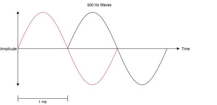
Between these two frequencies, the phase shift would change from 180º to 360º/0º and cause varying output levels across the summed frequency response.
Note that, in the example of a 1 ms delay, the lowest frequency to experience a 180º phase-shift is 500 Hz since its period is precisely 2 ms long. As the cycle/period time becomes longer, the 1 ms delay will have less and less effect on the summed output.
However, certain frequencies above this point will be subjected to 360 (+360 X) degree in-phase and 180 (+360 X) degree out-of-phase phase shifts along with all phase shifts in between.
To put that vague statement into general terms, we can look at the following equation:
\omega = 360 \cdot \frac{t}{p}where:
ω = phase shift (in degrees)
t = time difference between the original and shifted signal (in seconds)
p = period of the wave being shifted (in seconds)
Remember that if the ω = 360x (x is any integer number), the shifted signal will be 100% in phase.
It the ω = 360x + 180 (x is any integer number), then the shifted signal will be 100% out-of-phase.
To keep with our example of a 1 ms delay/phase-shift, our in-phase frequencies would be:
- 1 kHz
- 2 kHz
- 3 kHz
- 4 kHz
- 5 kHz, and so on
Here's a visual representation of 2 kHz sine waves with a 720º (0º) phase-shift caused by a 1 ms delay.

Our out-of-phase frequencies would be:
- 500 Hz
- 1.5 kHz
- 2.5 kHz
- 3.5 kHz
- 4.5 kHz, and so on
Here's a visual representation of 1.5 kHz sine waves with a 540º (180º) phase-shift caused by a 1 ms delay.

This kind of phase filtering produces what is known as a comb filter. A comb filter is named after its comb-like appearance in a frequency response graph or EQ. A comb filter caused by the aforementioned 1 ms delay can be visualized across the entire frequency spectrum in the illustration below:

When a signal is mixed in with a phase-shifted version of itself (as is the case with flanger), regularly spaced notches are created across the output frequency response.
Note that the notches seem like they’re getting closer and closer as the frequency increases. That’s because the frequency scale is logarithmic by nature.
By modulating the delay time between the original and phase-shifted signal, the resulting output comb filter will effectively be swept across the frequency spectrum. This is the flanger effect!
A Brief History Of The Flanger Effect
The flanger effect is named after its origins though the typical audio effects unit only mimics the original method's sound by electronic means.
In the context of audio, the term flange refers to the circular pieces at the exterior of a tape reel.
The flanger/flanging effect was first heard in the days of reel-to-reel tape recording when a recorded track would be duplicated onto two different tapes on two tape machines.
Two machines would be played in sync with each of their playback head outputs mixed to a third tape machine for recording. Maintaining sync was, of course, critical for maintaining a proper phase relationship between the two playback tapes.
As the analog reels spun to pass tape across the playheads and record head, their rotational speed could be slowed by applying gentle pressure to the flange of the reel.
As one reel was gently slowed, its tape playback would fall increasingly out of sync with the other tape. In other words, the phase would be continuously shifting against the phase of the other tape machine.
This gradual increase in phase shift would cause a sweeping comb filter in the audio at the record head. An effect we now know as flanger or, in this case, “tape flange.”
Before the tapes would become too out-of-sync, the engineer/artist would remove pressure from one tape reel and apply pressure to the other to bring them back into sync. This would result in a second flanger sweep.
Today, the effect is much more accessible and easier to achieve with dedicated flanger hardware and even more so with software plugins.
The Flanger Circuit Design
Now that we've discussed what the flanger effect is and how it came to be, let's dive into the basics of the typical flanger effect unit design.
Like many phase-shifting modulation effects (vibrato, chorus), flanger units are actually centred around a delay circuit and a low-frequency oscillator (LFO).
More specifically, the heart of the flanger circuit is a delay path with its delay time modulated by an LFO.
The most basic signal flow diagram of a flanger unit would resemble the following:

We already know what the flanger does. Now let's consider how it does it.
Starting with the input, we see that the dry signal is fed into the output mixer (to be mixed with the phase-shifted/delayed signal) and the delay line mixer. Remember that, to achieve the sweeping comb filter flanger effect, we need the out-of-phase destructive interference between two identical (or near-identical) signals that are just slightly out-of-phase.
The delay circuit (whether it's analog or digital) delays the dry signal and outputs the “phase-shifted” signal fed into the output mixer. The LFO alters the delay time parameter of the delay circuit.
In addition to sending the phase-shifted signal to the output mixer, the delay circuit also feeds its output back into its input via the feedback loop. By increasing the feedback, the notches and peaks of the resulting comb filter are accentuated and, therefore, the flanger effect increases in intensity.
To achieve this comb filtering, the modulated delay time of the delay line should be kept below 20 ms throughout the modulation. Longer delay times (especially if there is no feedback) will cause a chorus-like effect rather than a flanger effect.
Note that the LFO will have a frequency well below 20 Hz and even below 1 Hz in slower flanging effects. The waveform of the LFO is often a sine wave, though other shapes are certainly possible (triangle waves are also quite common).
Once again, as the LFO modulates the delay time, the resulting comb filter will be swept across the frequency range, and the flanger effect will occur.
Some flanger effects (there are always exceptions, aren't there?) may use something other than an LFO to modulate the delay time of the flanger's phase-shifting/delay line. Other modulation signals include:
- Manual voltage controls: a voltage control that is altered manually via a potentiometer or other tactile control.
- Control voltages (CVs): a separate inputted voltage source (signal) that may not necessarily be an LFO.
- Envelopes: a voltage profile generated by an envelope generator with defined attack, release, sustain and decay or, alternatively, an envelope that follows the amplitude of another signal, generated by an envelope follower/detector.
Flanger Parameters
Now that we understand what the flanger effect is all about, let's consider the various parameters that can be altered to hone in the performance of a flanger effect unit.
Flanger effect units/plugins will often have many (if not all) of the following controls:
Speed/Rate
The speed/rate parameter of a flanger controls the frequency of the LFO. This affects the rate at which the delay time of the flanger's delay circuit is modulated within its range and, therefore, the speed of the flanger effect.
All other parameters being equal, slower rates are usually better. However, faster speeds can also be used to achieve special effects.
Depth/Width
The depth/width parameter of a flanger controls the amplitude of the LFO, which ultimately controls the overall frequency range of the sweeping comb filter.
Manual
The manual parameter of a flanger will control the base delay time of the phase-shifting/delay circuit, about which the LFO will modulate. Therefore, this control will adjust the centre point about which the flanger's comb filter will sweep about in the resulting “EQ.”
Feedback/Resonance
The feedback (sometimes referred to as resonance or regeneration) parameter of a flanger unit will control the level of the delayed/modulated signal that is fed back through the phase-shifting/delay circuit.
Increasing the amount of feedback in the flanger will effectively increase the amplitude of the resonance peaks within the resulting comb filter. Increasing the feedback will have the effect of increasing the intensity of the flanger's sonic effect.
Let’s consider an image to help illustrate the effect feedback has on the flanger effect. In the following image, the red line represents a flanger's instantaneous comb filter at some point when no feedback is sent through the delay line. The blue line represents the same comb filter at the same instant in time if the flanger's feedback control was turned up:

Mix
The mix/blend parameter of a flanger effectively mixes the phase-shifted signal with the direct/dry signal at the unit/plugin's output.
If a flanger pedal doesn’t have a mix control, the wet/dry blend is typically 50/50, where the most phase cancellation will occur.
Flanger Effect Unit/Plugin Examples
Before we wrap things up, it’s always a great idea to consider some examples. Let’s have a look at 5 different flangers to help solidify our understanding of this modulation effect.
In this section, we’ll discuss:
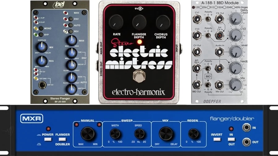
- 500 Series flanger unit: Bel BF-20-500
- 19″ rack mount flanger unit: MXR-126 Flanger Doubler
- Flanger effect pedal: Electro-Harmonix Stereo Electric Mistress
- Flanger Eurorack module: Doepfer A-188-1 BBD
- Flanger plugin: D16 Group Antresol
Bel BF-20-500
The Bel BF-20-500 is a 500 Series version of Bel's BF-20 rack-mount stereo flanger from the 1970s.

The Bel BF-20-500 offers 3 distinct modes of operation:
- Manual: the user has complete control over the degree of flanging produced and when it occurs.
- Envelope: an envelope follower is set to trigger flanging. The trigger can either be the source material itself or a separate external source (control voltage) via the front panel 1/4″ jack.
- Auto: the BF-20-500 provides continuous flanging based on the settings of the Auto controls.
This superb flanger utilizes SAD512 bucket-brigade (BBD) delay devices in an all-analog signal path.
MXR-126 Flanger Doubler
The MXR-126 Flanger Doubler is a rack-mount unit from the 1970s with both flanger and doubler effect capabilities.

The “doubler” effect of the MXR-126 involves a slight unmodulated delay. When this delay is modulated, however, we get into the territory of flanging.
The 126 uses two BBD devices: the popular Reticon SAD1024 and the lesser-known Reticon R5101.
As for controls, the relatively straightforward MXR-126 has a switch two toggle between the Double and Flanger modes and a switch to invert the signal's polarity.
It has a manual control that allows users to sweep the flanger effect manually along with sweep controls (a width and speed knob) that will automatically sweep the flanger instead.
The mix control effectively mixes the dry and delayed (phase-shifted) signals together, and the regen control adjusts the feedback of the circuit and the resonance of the flanger effect.
Electro-Harmonix Stereo Electric Mistress
The Electro-Harmonix Stereo Electric Mistress is a popular and well-respected flanger guitar pedal and stereo version of the legendary Electric Mistress flanger.

This classic pedal was first released in 1975 as the first-ever stompbox flanger unit.
This pedal offers a beautiful mix of two modulation favourites: flanger and chorus.
Part of the beauty of the Stereo Electric Mistress is its simplicity. There are 3 basic controls:
- Rate knob: controls the rate/speed of the flanger and chorus circuits.
- Above the 10 o’clock position, the knob controls the rate of an LFO that modulates the flanger and chorus.
- Below the 10 o’clock position, the knob is in Filter Matrix mode where we can manually modulate the flanger and chorus.
- Flanger Depth knob: controls the amount of the flanger-affected signal that is mixed with the direct signal.
- Chorus Depth knob: controls the amount of the chorus-affected signal that is mixed with the direct signal.
And only two of those knobs affect the flanger. Of course, using both effects simultaneously is one of the benefits and characteristics of this awesome pedal.
Doepfer A-188-1 BBD
The Doepfer A-188-1 BBD is a bucket brigade device delay unit capable of achieving flanger and chorus effects along with Karplus/Strong synthesis.

This powerful BBD module can produce a variety of flanger and flanger-like effects. It has manual control, 2 control voltage inputs and polarity switches for pretty much every possible signal.
To understand this module fully, please check out the manual at Doepfer.
Softube has developed a Doepfer A-188-1 BBD plugin for its Modular virtual synth instrument.
D16 Group Antresol
The D16 Group Antresol is a plugin emulation of the aforementioned original Electric Mistress flanger from Electro-Harmonix with additional functionality.

The highly tweakable flanger plugin has plenty of controls to adjust and presets to choose from. The plugin emulates the sound and functionality of BBD analog delay lines with stunning precision, bringing analog sound to the digital realm.
The stereo functionality offers optional independent parameter control for each stereo channel and selectable left/right or mid/side stereo processing modes.
The plugin features 3 different LFO-to-BBD clock curves, and the LFO can be synchronized to the DAW's tempo. It also has a low-cut filter, preamp, and detailed mixing section.
Offset, rate, depth and phase-shift controls are adjustable for each flanger channel.
Call To Action!
Experiment with flanger effects, whether they be plugins or hardware. Listen critically to how the modulation changes the sound over time. Adjust the parameters to get a sense of the extremes.
Find and listen to songs that utilize the flanger effect to really internalize its sound and how it's used.
Have any thoughts, questions or concerns? I invite you to add them to the comment section at the bottom of the page! I'd love to hear your insights and inquiries and will do my best to add to the conversation. Thanks!
Related Questions
What's the difference between flanger and phaser? Flangers and phasers both produce their sonic effect by introducing phase-shifting into a signal and controlling such phase-shifting with an LFO. Flangers utilize a delay circuit and modulate the delay time to achieve their effects, while phasers utilize all-pass filters and modulate the corner frequencies.
What are audio modulation effects? Audio modulation effects manipulate the input audio over time via the control of a carrier signal. The input audio is referred to as the modulator signal, which technically controls the carrier signal, which is generally produced via an oscillator generator or signal detector.
Related Articles
To learn more about phaser and modulation effects more generally, check out the following articles:
• Complete Guide To The Phaser Audio Modulation Effect
• Complete Guide To Audio Modulation Effects (With Examples)

