Complete Guide To Audio Equalization & EQ Hardware/Software

Equalization (EQ) is one of the most important tools when it comes to audio mixing. EQ, when used correctly, will have a place in nearly all signal chains, working to improve the overall quality of the audio and the mix itself.
What is audio equalization? EQ is the process of adjusting the balance between frequencies within an audio signal. This process increases or decreases the relative amplitudes of some frequency bands compared to other bands with filters, boosts and cuts. EQ is used in mixing, tone shaping, crossovers, feedback control and more.
In this complete guide to audio equalization, we'll be discussing EQ in great depth, touching on how EQ works, the types of EQ with hardware and software examples, how to use EQ in different situations, and more.
Note that this article is well over 10,000 words long. I've added hyperlinks to jump around the article for quicker reading and links to more concise articles on several topics included in this complete guide.
If you'd like to support my work and learn more about music production, please consider subscribing to my Substack.
What Is Audio Equalization?
In the opening, I gave a quick answer about how EQ effectively adjusts the balance of frequencies within an audio signal. Let's elaborate upon this definition to better our understanding of audio equalization.
With equalization, we can effectively bring up the amplitude of some frequencies relative to others or, conversely, bring down the amplitude of some frequencies relative to others. This is known, generally, as boosting and cutting, respectively.
EQ can be used to boost or cut specific frequency bands or frequencies above or below a certain point. It can even be used to eliminate frequencies entirely within a specified frequency band or above or below a certain cutoff frequency point—more on this in the section on filters.
Another way of looking at EQ is as a frequency-specific volume/gain control. We can turn some frequencies up while turning others down.
The frequencies affected by EQ are typically referred to a “bands”. A band of frequencies is essentially a defined range of frequencies between a minimum point and a maximum point. The frequency spectrum of audio/sound waves is continuous, so EQ doesn't only affect a single specified discrete frequency.
Adjusting the relative amplitudes of defined frequency bands may seem like an unnatural and undesirable effect to process audio with. However, EQ is actually one of the most important tools for working with audio, period.
From studio and live mixes to speaker design and even to more surprising applications like phasers, EQ is a critical tool for working with audio.
In this complete guide to audio equalization, I'll do my best to prove that to you!
A Note On Human Hearing
Before we get too deep into EQ, I'd like to go over a few basics of human hearing.
The universally accepted audible range of frequencies is defined as 20 Hz to 20,000 Hz. Hertz (Hz) refers to the number of cycles per second a sound wave (or an audio signal that represents a sound wave) will vibrate/oscillate.
EQ typically works on the audible frequency range between 20 Hz and 20,000 Hz though some EQ units are capable of affecting frequencies beyond this audible range.
Unless we're working with pure, undistorted sine waves, a sound or audio file will contain multiple frequencies (some are harmonic, some are inharmonic, and some are just noise).
Many people have sustained hearing damage or have otherwise lost the ability to hear the upper range, so the 20 kHz upper limit is often lower.
The low-end of the audible range is felt more than it is heard. It also generally takes up more energy in a mix and sound transmission.
The way we hear sound is also dependent on the loudness of such sound. This can be summed up in the Fletcher-Munson curves, which I'll post below:

Let's define the axes and the line:
- Frequency in Hz (Y-axis): the frequency of the sound waves. Frequencies of varying amplitudes make up the timbre of a sound. Hertz (Hz) refers to cycles per second.
- Sound Pressure Level in dB SPL (Y-axis): the ratio of sound pressure against the hearing threshold reference level. The greater the SPL, the “louder” any particular frequency will be perceived. Decibels (dB) refer to a logarithmic ratio.
- Phon (curves): a logarithmic unit of loudness level that takes into account the varying hearing sensitivity across the audible spectrum.
So by looking at the Fletcher-Munson curves, we can see that we're most sensitive to frequencies in the 2 kHz – 5 kHz range. We can also see that low-end frequencies will require much higher SPLs and energy in order to be perceived as loud as higher frequencies. The same is true of the very high-end relative to the mid-range.
I just wanted to preface the rest of this article with this primer on human hearing. This little bit of knowledge will help us to comprehend EQ throughout this guide.
Let's Begin With The Filters
To understand audio equalization, it's imperative that we understand the filters that largely makeup EQ.
As I began writing this section, I came to realize how deep and complex the study of electronic filters can be. For the sake of keeping the length of this article short and focusing more on EQ rather than filter theory, I'll cover the most important filter types in some detail; briefly mention noteworthy filter styles/types, and link to more detailed articles when appropriate.
Before we get into our discussion on filters, let's go over some “housekeeping” definitions.
Passband/Bandwidth: the passband or bandwidth of a filter refers to the frequency range(s) the filter “passes”. These bands are defined up the -3 dB cutoff frequency point(s) of the filter.
Stopband: the stopband of a filter refers to the frequency range(s) the filter effectively filters out. A stopband attenuation level is generally set, and any frequencies at or beyond this level (typically measured in -dB) are considered in the stopband. Some filters will have a flatline stopband or stopbands with their own stopband cutoff frequencies with other filters roll-off to infinity.
Transition Band: the transition band(s) of a filter are the frequency range(s) between the passband and stopband limits.
Roll-Off/Slope: the roll-off (sometimes called the slope or skirt) of a filter is the rate at which attenuation happens in the transition band(s). Roll-off is generally defined as decibels for octave (dB/octave) or decibels per decade (dB/decade).
Octave: an octave up refers to a doubling of frequency, and an octave down refers to a halving of frequency.
Decade: a decade up refers to a tenfold increase of frequency, and an octave down refers to a tenfold decrease of frequency.
Cutoff Frequency: the cutoff frequency (also known as the corner or break frequency) is the point at which a filter attenuates (or boosts) the signal by 3 dB. It marks the point between the passband and transition band and defines the limits of the filter's bandwidth.
Centre Frequency: the centre frequency (also known as the resonance peak) applies to band-pass and bandstop filters along with EQ bell/peak filters and marks the centre of the filter's bandwidth. The square of the centre frequency is equal to the product of the two cutoff frequencies.
Phase-Shift: phase-shift is defined as any change in phase a filter's output will have compared to its input. Unless the filter/EQ is designed to be linear phase, it will produce some amount of phase-shift.
Q Factor: Q factor is defined as the ratio of the centre/resonant frequency to the bandwidth of the filter. Higher Q factors lead to narrower transition bands.
With that out of the way, let's get into the basics of audio filters!
In this section, we'll discuss the following:
- What Is An Audio Filter?
- Analog Vs. Digital Filters
- Active Vs. Passive Filters
- The Order Of Filters
- Low-Pass Filter
- High-Pass Filter
- Band-Pass Filter
- Band-Stop Filter
- Bell Curve/Peak Filter
- Low Shelf Filter
- High Shelf Filter
- Brickwall Filter
- All-Pass Filter
- Filter Class/Alignment
What Is An Audio Filter?
What is an audio filter? An audio filter is a frequency-dependent amplifier (or attenuator) circuit that works within (and beyond) the audio frequency range of 20 Hz to 20,000 Hz. There is a wide variety of filters, some of which amplify/boost, attenuate/cut and/or pass defined frequency ranges/bands.
When it comes to audio equalization, we can use the term filter to refer to individual bands of an equalizer. This makes filters an important part of equalization and our comprehension of EQ.
Filters are certainly used in EQ units (both hardware and software) and can be found on other devices that offer some amount of tone control or EQ capabilities.
The Ideal Filter
What is an ideal filter in audio? An ideal filter (also known as a “brickwall” filter) is a filter without any transition band. It passes every frequency within its passband perfectly and completely eliminates every frequency in its stopband.
Ideal filters are just that, “ideal”. They are not truly possible in practice, though some filter types can closely approximate them.
The following image will illustrate (from left to right) an ideal low-pass, high-pass, band-pass and bandstop filter.

Analog Vs. Digital Filters
Analog filters work on analog audio signals and are made of circuits with analog components (resistors, capacitors, inductors, operation amplifiers, etc.). Digital filters, on the other hand, work on digital audio signals and are embedded in digital chips or within software coding.
Analog filters (along with analog audio) are considered to be “continuous-time,” while digital filters (along with digital audio are considered to be “discrete-time (sampled)”.
Analog filters are generally simple in design though they increase in complexity as their designs approach the performance of an “ideal filter”. Many digital filters (including EQ plugins) emulate these analog filters.
Because analog designs are easier to explain and work with (I'm not a computer engineer), I'll stick to explaining the following filter types with basic analog schematics rather trying to fool myself and you about how digital chips work.
Digital filters are often more precise and much more flexible in design due to the expansive nature of digital signal processing (DSP). The exactness of their design makes them much more accurate to their given parameters. In contrast, analog filters are somewhat limited by the accuracy of their components and the signal path at large.
Digital filters also come with the benefits of an improved cost-to-benefit ratio and a more consistent nature in temperature and humidity changes.
Analog filters, of course, benefit from working on a continuous spectrum.
Note that some digital EQs are designed to emulate the performance of analog EQs. We can find plenty of EQ plugins that aim to emulate classic or other analog equalizers.
Active Vs. Passive Filters
As their name suggests, passive filters utilize only passive components (resistors, capacitors, inductors, etc.) and do not require any power when filtering an audio signal.
On the other hand, active filters will utilize active components, such as operational amplifiers, in addition to resistors and capacitors (though not inductors due to issues of size and distortion at lower frequencies). These filters do require external power in order to output a filtered signal.
Note that capacitors are typically preferred over inductors in audio filters because they are more reactive (less resistive) than inductors (“purer” for AC signals like audio) and are less prone to noise and coupling with other components within the system.
With passive filters, the output signal ends up having a lower amplitude than in the input signal. The gain is never greater than unity, and the load impedance will also play a role in the filter's sound, particularly on the filter's cutoff frequency.
For every additional order of a passive filter, there is additional attenuation. Attenuation can be reversed via amplification, which brings us to active filters. Active filters effectively draw power from an external source for the purpose of amplifying the output signal.
In addition to general amplification, the op-amps used in active filters also help tremendously in taming the impedance of the overall filter circuit. An op-amp will act as a sort of buffer, having a very high input impedance and a low output impedance. These traits make the active filter much more consistent in its operation. The connected load will have little impact on the filter's performance (unlike with passive filters).
Though more complex, active filters are often easier to design and produce superior results over many of their passive counterparts.
Equalizers are generally active. Otherwise, they wouldn't be able to boost certain bands. However, there are passive equalizers as well, which we'll discuss later in this article.
The Order Of Filters
What is the order of a filter in audio? The order of a filter refers to the slope of that filter's transition band (roll-off rate). It is an integer number that, in analog filters, is defined by the number of reactive components in the filter circuit. For every integer increase in order, the roll-off rate steepens by 6 dB/octave (20 dB/decade).
Audio filters (and other electrical filters) can be classified by their order. The order is an integer number and is typically the same as the number of poles.
The order of a filter, in the analog world, indicates the minimum number of reactive electrical components the filter will require in its design. Reactive electrical components include capacitors and inductors. Higher-order filters, then, are generally more complex and expensive.
The images below show basic schematics for a first-order passive low-pass filter and a second-order Sallen-Key unity-gain low-pass filter. Notice how the first-order filter has a single capacitor (one reactive component), and the second-order filter, though it includes an op-amp, has two capacitors (two reactive components).


Every reactive component within an analog filter circuit will add 90º of phase-shift.
There are two key points to know about filter order:
- Each integer increase in order will steepen the roll-off rate (of high-pass and low-pass filters) by 6 dB/octave or 20 dB/decade (these rates are equal).
- Each integer increase in order will cause [at least] another 90º of total phase-shift between the passband and stopband of the filter's output signal.
Note that band-pass and band-stop filters each utilize both an LPF and HPF. A second-order band-pass or bandstop filter will have a first-order LPF and a first-order HPF, each having a roll-off rate of 6 dB/octave (20 dB/decade).
The higher the order, the more closely the filter's transition band will resemble that of an ideal filter.
Here's a table and graph to show the roll-offs of each filter order:
| Filter Order | Roll-Off Per Octave | Roll-Off Per Decade |
|---|---|---|
| 1st Order | -6 dB/oct | -20 dB/dec |
| 2nd Order | -12 dB/oct | -40 dB/dec |
| 3rd Order | -18 dB/oct | -60 dB/dec |
| 4th Order | -24 dB/oct | -80 dB/dec |
| 5th Order | -30 dB/oct | -100 dB/dec |
Here's a simple graph of low-pass filters (with orders 1 through 5) with a cutoff frequency of 100 Hz. Note that the cutoff frequency happens at the point where there is 3 dB of attenuation from the original level (that is part of the definition of cutoff frequencies).

Note that the greater the order, the sharper the roll-off.
Generally speaking, the higher the order, the more closely the filter will approximate a perfect filter (that is, a filter that passes a finite block of frequencies unaltered while completely removing frequencies outside the passband from the signal). This ideal filter is sometimes referred to as a “brickwall filter” and is represented by the yellow in the image below:

And with that, let's get into the general types of filters we'll come across in audio equalizers.
Low-Pass Filter
What is a low-pass filter in audio? A low-pass filter (LPF) “passes” the low-frequencies below their cutoff frequency while progressively attenuating frequencies above their cutoff. In other words, low-pass filters remove high-frequency content from an audio signal above a defined cutoff point.
Low-pass filters are sometimes referred to as “high-cut” filters, and both names accurately describe the functionality of these filters.
Let's have a look at a graphical representation of a low-pass filter. Note that the cutoff frequency (fC) is a the -3 dB point, and frequencies above this point are gradually filtered out:

Here's a representation of a basic first-order active analog low-pass filter with gain:

Here is a couple of graphs showing the typical frequency response and phase-shift of an analog first-order low-pass filter. Remember that, by increasing the order, we would steepen the roll-off and cause the maximum phase-shift to increase by 90º (the phase-shift at fC would be -90º in this case):

Please note that the actual phase response of this example and all of the following filter examples could be set between two different points if the filter was inverted.
High-Pass Filter
What is a high-pass filter in audio? A high-pass filter (HPF) “passes” the high-frequencies above their cutoff frequency while progressively attenuating frequencies below the cutoff frequency. In other words, high-pass filters remove low-frequency content from an audio signal below a defined cutoff point.
High-pass filters are sometimes referred to as “low-cut” filters, and both names accurately describe the functionality of these filters.
Let's have a look at a graphical representation of a high-pass filter. Note that the cutoff frequency (fC) is a the -3 dB point, and frequencies below this point are gradually filtered out:

Here's a representation of a basic first-order active analog high-pass filter with gain:

Here is a couple of graphs showing the typical frequency response and phase-shift of an analog first-order high-pass filter. Remember that, by increasing the order, we would steepen the roll-off and cause the maximum phase-shift to increase by 90º (the phase-shift at fC would be +90º in this case):

Band-Pass Filter
What is a band-pass filter in audio? A band-pass filter “passes” a band of frequencies (a defined range above a low cutoff frequency and below a high cutoff frequency) while progressively attenuating frequencies below the low cutoff and above the high cutoff.
A band-pass filter is a combination of a low-pass and high-pass filter cascaded together. It passes a band of frequencies (a defined range with a low cutoff and a high cutoff) while progressively attenuating frequencies below the low cutoff and above the high cutoff.
Let's have a look at a graphical representation of a band-pass filter. Note that the low cutoff frequency (fL) and the high cutoff frequency (fH) are at the -3 dB points. Frequencies below fL and above fH are gradually filtered out:

Here's a representation of a basic second-order active analog band-pass filter with a gain/buffer stage after each first-order filter:

Here is a couple of graphs showing the typical frequency response and phase-shift of an analog second-order band-pass filter (with first-order HPF and LPF). Remember that, by increasing the order of the LPF and HPF, we would steepen the roll-offs and cause the maximum phase-shift to increase by 90º each way. The phase-shift at fC would remain at 0º, but the maximum would extend to +180º at the low frequencies, and the minimum would extend to -180º at the high frequencies:

Band-Stop Filter
What is a band-reject filter in audio? A band-stop filter (aka band-reject or notch filter) works by removing frequencies in a specified band within the overall frequency spectrum. It allows frequencies below the low cutoff frequency to pass along with frequencies above the high cutoff frequency.
A band-stop filter is often referred to as a band-reject filter or, more commonly, in EQ, as a notch filter. It is kind of like the opposite of a band-pass filter and can be thought of as a combination of a low-pass and a high-pass filter in a parallel configuration.
Let's have a look at a graphical representation of a band-stop filter. Note that the low cutoff frequency (fL) and the high cutoff frequency (fH) are at the -3 dB points. Frequencies above fL and below fH are gradually filtered out:

Here's a representation of a basic second-order active analog band-stop filter with a buffer after each filter and an amplifier stage:

Here is a couple of graphs showing the typical frequency response and phase-shift of an analog second-order band-pass filter (with first-order HPF and LPF). Remember that, by increasing the order of the LPF and HPF, we would steepen the roll-offs and cause the maximum phase-shift to increase by 90º each way (the phase-shift at fC would peak at -180º and +180º and would extend to 0º toward 0 Hz and ∞ Hz).

Bell Curve/Peak Filter
What is a bell curve filter in audio? A bell curve filter is a filter capable of producing resonance (boost in EQ) or anti-resonance (cut in EQ) around a specified centre frequency. These filters are defined by a central frequency, Q factor (width of the boost/cut) and relative gain.
A bell EQ is perhaps the most commonly-used control in dedicated EQ units. These filters are used in the bands of a graphic EQ and are sweepable in a parametric EQ.
Unlike the low/high-pass and low/high shelf filters, which can only affect frequencies above or below a set point, bell EQ affects the amplitude at (and around) a set point.
This can be visualized in the following illustrations of a bell boost and cut, respectively:


Three factors define the response of a bell EQ:
- Frequency
- Bandwidth or Q (quality factor)
- Gain
Frequency refers to the centre point of the bell EQ filter. This is the frequency at which the boost or cut will be at its maximum. This is measured in Hertz (Hz)
The bandwidth is the frequency range between the -3 dB low and high cutoff frequencies (in boosts and cuts greater than 3 dB) or the “half-gain” cutoff points (in boosts and cuts less than 3 dB).
Q (quality factor) is dimensionless and refers to how narrow/steep or wide/gentle the boost or cut will be. Though it's generally calculated as the inverse of the bandwidth, different EQs will give different results. However, what remains consistent is that a higher Q will produce a narrower band in which a smaller range of frequencies is affected.
Again, this is general, but Q = fC / BW = √fHfL / fH – fL is the typical equation.
Gain is measured in decibels (dB) and refers to the relative change in amplitude caused by the bell EQ. Boosts will have positive gain, while cuts will have negative gain. Note that “gain” here is only relative to the 0 dB “starting point” of the overall EQ.
Here are a couple of graphs showing the typical frequency response and phase shift of an analog bell/peak filter. Remember that, by increasing the Q, we would narrow the bandwidth and steepen the roll-offs. If we increased the gain (boosting or cutting), we would increase the phase shift. In these examples, the slope is about 12 dB/oct with a Q of about 1.7:


Note that, in linear phase EQ designs where the phase remains 0º across the frequency spectrum, a bell boost can be thought of as a parallel processing and mixing of a dry signal and a duplicated band-passed signal.
Conversely, but still within a linear phase EQ design, a bell cut can be thought of as a parallel processing and mixing of a dry signal and a duplicated band-stopped signal.
Low Shelf Filter
What is a low-shelf filter in audio? A low shelf filter is a filter that either boosts (increases amplitude) or cuts (decreases amplitude) frequencies below a certain cutoff frequency. These filters generally have a well-defined transition band and a levelling-off of amplitude in the lower end.
Low shelf filters may have a fixed or variable slope (dB/octave or dB/decade). In parametric and digital filters, they will often have a variable Q factor that will further adjust the slope and width of the transition period and even introduce resonances and ripple into the passband and shelf amplitude.
In the illustrations below, you'll see a visual representation of the amplitude and phase graphs of a low-shelf boost and low-shelf cut, respectively:


Note that, in linear phase EQ designs, a low-shelf boost can be thought of as a parallel processing and mixing of a dry signal and a duplicated low-passed signal.
Conversely, but still within a linear phase EQ design, a low-shelf cut can be thought of as a parallel processing and mixing of a dry signal and a duplicated high-passed signal.
High Shelf Filter
What is a high-shelf filter in audio? A high shelf filter is a filter that either boosts (increases amplitude) or cuts (decreases amplitude) frequencies above a certain cutoff frequency. These filters generally have a well-defined transition band and a levelling-off of amplitude in the upper end.
High shelf filters may have a fixed or variable slope (dB/octave or dB/decade). In parametric and digital filters, they will often have a variable Q factor that will further adjust the slope and width of the transition period and even introduce resonances and ripple into the passband and shelf amplitude.
In the illustrations below, you'll see a visual representation of the amplitude and phase graphs of a high-shelf boost and high-shelf cut, respectively:


Note that, in linear phase EQ designs, a high-shelf boost can be thought of as a parallel processing and mixing of a dry signal and a duplicated high-passed signal.
Conversely, but still within a linear phase EQ design, a high-shelf cut can be thought of as a parallel processing and mixing of a dry signal and a duplicated low-passed signal.
Brickwall Filter
What is a brickwall filter? A brickwall filter is a close approximation to an ideal filter (typically on a low-pass or high-pass filter) that has an extremely narrow transition band and an extremely steep slope. Phase distortion is to be expected unless the brickwall filter is part of a maximally linear phase EQ.
Here is a representation of the amplitude graph of a brickwall low-pass and high-pass filter, respectively. The phase graph should be expected to yield rather unpredictable results, so I'll leave it out.


Note that brickwall filters are not found in the majority of equalizers. They are typically found in EQ plugins.
All-Pass Filter
What is an all-pass filter in audio? An all-pass filter allows all frequencies to pass with unchanged amplitude but will shift the phase across the frequency response. All-pass filters produce varying delay across the frequency response in order to produce this phase shift.
All-pass filters are odd. They do not actually filter any frequencies in terms of amplitude. They pass all frequencies.
Rather, they work by affecting the phase of any given sinusoidal component (frequency) according to its frequency.

An all-pass filter can be thought of as a low-pass and high-pass filter run in parallel so that all frequencies are passed. The catch is that there is a phase inverter in front of one of the filters, so that phase goes from 0º to 180º (or -180º) across the frequency spectrum.

We produce the phaser effect by cascading several all-pass filters together in a circuit and modulating their frequencies with a low-frequency oscillator (LFO). This can be visualized by the phase cancellations shown below (more on this later):


More Filters Defined
Though the filters above are generally what we'll find in EQ (other than the all-pass filter), I'll briefly run through other filter definitions to give you some extra information. In this section, I'll go over:
- Infinite impulse response filter
- Finite impulse response filter
- Coincident-pole filter
- Butterworth filter
- Chebyshev filter
- Bessel filter
- Elliptic filter
- Comb filter
- Convolution filter
What is an infinite impulse response filter in audio? An IIR filter is a linear time-invariant analog type of filter (that has been digitized as well) that works with an impulse response that continues indefinitely, never becoming exactly zero. Butterworth, Chebyshev, Bessel and elliptic filters are examples of IIR filters.
What is a finite impulse response filter in audio? An FIR filter is a filter (analog or digital, though nearly always digital) that works with an impulse response of finite duration, settling to zero within some amount of time. It lends itself well to linear phase EQ.
What is a coincident-pole filter in audio? A coincident-pole filter is a filter made of multiple single-pole (first-order) filters in cascade or series. For each additional pole/order, the transition band slope increases by 6 dB/octave (20 dB/decade).
What is a Butterworth filter in audio? A Butterworth filter (maximally flat magnitude filter) is a linear analog filter designed to have a frequency response as flat as possible in the passband. Butterworth filters do not offer an overly steep roll-off and are often used in low/high-pass and low/high shelf filters.
What is a Bessel filter in audio? A Bessel filter is a linear analog filter with a maximally flat group or phase response to preserve the wave shapes of signals within the passband. Bessel filters provide a gentle frequency roll-off beyond the cutoff frequency and are mainly designed for linear phase response with little overshoot.
What is a Chebyshev filter in audio? A Chebyshev filter is a linear analog filter designed to have a very steep roll-off at the expense of passband ripple (type I) or stopband ripple (type II/inverse).
What is an elliptic filter in audio? An elliptic filter (also known as a Cauer filter) is a linear analog filter with equalized ripple in both the passband and the stopband. It offers a very steep transition band.
What is a comb filter in audio? Comb filtering results in regular notches within the frequency response of an audio signal that are multiples of some fundamental frequency. Comb filtering happens when a signal is delayed by a very short time and mixed with the original signal (flanger) or, acoustically, near reflective boundaries.
Typical EQ Parameters/Controls
Before we get into the types of equalizers, let's discuss the typical parameters and controls we'll encounter with EQ units. This way, I can name a parameter or control in the following sections without explaining it on the spot.
The EQ parameters and controls we'll discuss are:
Gain (Boost/Cut)
Gain, measured in decibels, refers to the relative amplitude applied to any of the bands within an EQ.
Negative gain means the attenuation of a band and is considered to be a “cut”. Positive gain means amplification of a band and is considered to be a “boost”.
Note that low-pass, band-pass, high-pass and band-stop/notch filters will not have a gain control as they're designed to eliminate frequencies above, above and below, below and between cutoff frequencies, respectively. Therefore, their “gain” value would be negative infinity (though the downward slope would technically only ever approach negative infinity).
Bandwidth
Bandwidth isn't a very common control on audio equalizers. Rather, the Q (which we'll get to in a minute) is the more popular parameter, which is the inverse of the bandwidth.
However, for those EQ units with bandwidth controls, and for a primer before our discussion on Q, let's discuss what bandwidth is.
The bandwidth of any boost/cut (bell/peak-type or band-stop/notch filter) is defined as the frequency range affected by such a boost or cut.
But there's a more technical definition of bandwidth. Bandwidth is defined as the difference between the high cutoff frequency (fH) and the low cutoff frequency (fL). These cutoff frequencies (sometimes referred to as corner, crossover or half-power frequencies) happen where the boost or cut is 3 decibels less than the boost or cut's maximum value, which happens at the centre frequency.
This typical bandwidth can be visualized in the following image:

Of course, there are plenty of situations where the boost or cut of a bell-type filter is less than 3 dB, and this way of calculating bandwidth falls apart. In these situations, manufacturers sometimes use “half-gain bandwidth” where the fH and fL are the points where the boost or cut are at the halfway point between the peak of the filter and the setpoint from where the filter is referenced.
This half-gain bandwidth can be visualized in the following image:

Although these are the typical methods in which bandwidth is calculated, equalizers are not necessarily bound to these strict definitions (though it would help our understanding if they were).
Quality Factor (Q)
The quality factor (referred to simply as “Q”) is the ratio of the centre/resonant frequency to the bandwidth of the filter.
Q=\frac{f_C}{BW}=\sqrt{\frac{f_Hf_L}{f_H-f_L}}where:
• fC: centre/resonant frequency
• fH: high cutoff frequency (where the signal drops off by 3 dB)
• fL: low cutoff frequency (where the signal drops off by 3 dB)
• BW: bandwidth
Q is dimensionless and refers to how narrow/steep or wide/gentle the boost or cut will be. A higher Q will produce a narrow band in which a smaller range of frequencies is affected.
Note that Q will maintain the same shape across a logarithmic frequency scale. In other words, a fixed Q value will provide a bandwidth across a set fraction/multiple of octaves regardless of its centre frequency.
For example, if a Q value sets a bandwidth of two octaves, a centre frequency of 100 Hz would have a bandwidth from 50 Hz to 200 Hz. If the centre frequency were 2,000 Hz, the same Q value would yield a bandwidth from 1,000 Hz to 4,000 Hz.
By the -3 dB definition of bandwidth, Q is simply “Q”. By the aforementioned “half-gain bandwidth”, we have “half-gain Q”, or “Robert Bristow-Johnson's (RBJ) Q”.
That all being said, different parametric EQs will give different bandwidths with the same Q values. So, then, the technical stuff we've discussed is useful to know but not absolutely correct in all cases. For more information on discrepancies between various PEQs, check out this awesome resource on Q values of common PEQ plugins.
The main takeaway here is that by increasing the Q, we narrow the bandwidth (whatever it happens to be), and by decreasing the Q, we widen the filter's bandwidth. This is certainly the case with any EQ that has Q controls!
If we go by the -3 dB cutoff frequency points, we'd have the following table relating Q factors to bandwidths (measured in octaves):
| Bandwidth (measured in octaves) | Q Factor |
|---|---|
| 3 | 0.404 |
| 2.5 | 0.511 |
| 2 | 0.667 |
| 1.5 | 0.920 |
| 1 | 1.414 |
| 2/3 | 2.145 |
| 1/2 | 2.871 |
| 1/3 | 4.318 |
| 1/6 | 8.651 |
Centre Frequency
Centre frequency parameters (sometimes called resonance frequency controls) allow us to control the fR value of the bell or notch filter(s) of an EQ unit.
Cutoff Frequency
Cutoff frequency parameters allow us to control the cutoff frequencies of high-pass, low-pass and band-pass filters. Note that the cutoff frequencies, like the aforementioned high and low cutoff frequencies of the general bandwidth equation, happen at the point where the filter attenuates 3 dB from the original source.
Here's an illustration of a band-pass filter with both low (fL) and high cutoff frequencies (fH) marked:

Slope
Some equalizers will have slope controls to adjust the roll-off rate of the individual filters. These controls effectively alter the order of the filter in question, causing the slope (defined in dB/octave and/or dB/decade) to change. Some EQs even offer a brickwall setting.
I'll re-post the table of filter orders (from 1st to 5th) and their respective slope here:
| Filter Order | Roll-Off Per Octave | Roll-Off Per Decade |
|---|---|---|
| 1st Order | -6 dB/oct | -20 dB/dec |
| 2nd Order | -12 dB/oct | -40 dB/dec |
| 3rd Order | -18 dB/oct | -60 dB/dec |
| 4th Order | -24 dB/oct | -80 dB/dec |
| 5th Order | -30 dB/oct | -100 dB/dec |
Types Of Equalizers
The importance of EQ has brought about several different types of EQ. Let's have a look at the various types of audio equalizers.
In this section, we'll discuss the following EQ types:
- Graphic EQ
- Parametric EQ
- Semi-Parametric-EQ
- Dynamic EQ
- Linear Phase EQ
- Passive EQ
- A Note On Shelving EQ
- Stereo EQ
- Mid-Side EQ
Graphic EQ
What is graphic audio equalization? Graphic equalization is a style of EQ where predetermined bands, centred around set frequencies with set Q factor values, can be either boosted or cut. The name comes from the fact that the EQ settings of a graphic EQ unit typically look very obvious and “graphic”.
Graphic EQ is easy to understand but limited in its flexibility to EQ audio. It gives us a set number of bands centred around set frequencies with fixed quality factors (Q). The “filters” within a graphic EQ are of the bell-type mentioned previously. We chose whether to boost or cut at any of these bands.
Graphic EQs are laid out with a bank of slider controls that we can use to boost or cut these frequency bands. By adjusting these faders, we can see graphically, how the EQ will shape the sound across the frequency spectrum.
The greater the number of bands in a graphic EQ will typically mean a narrower bandwidth per band (to fit all the bands within the audible spectrum). A graphic EQ with more faders/bands will offer greater control and resolution over the equalization of the signal it's processing.
It's important to note that each band filter within an analog graphic EQ will have its own filter circuit and introduce its own noise and phase manipulation. Each filter of a graphic EQ is likely to overlap its neighbouring filters. This can lead to imperfect results and messy phase responses.
A common design in professional graphic EQs is one with 31 bands where the centre frequency of each band is spaced logarithmically, roughly 1/3 of an octave from the adjacent bands. This is the case with the dbx 231s.
Graphic EQs are great for general EQ shaping and “tuning” rooms.
- Notable 500 Series graphic EQ unit: BAE G10
- Notable 19″ rack mount graphic EQ unit: dbx 231s
- Notable graphic EQ effect pedal: MXR M108S Ten Band EQ
- Notable graphic EQ Eurorack module: Music Thing Modular Graphic EQ
- Notable graphic EQ plugin: Waves GEQ

Parametric EQ
What is parametric audio equalization? Parametric EQ offers full customization of the frequency bands, including the choice of filter type, centre frequency, Q factor value and relative gain (boost/cut).
A parametric EQ gives us continuous control over all the important parameters. These parameters differ depending on the filter type (which is often selectable, especially with EQ plugins). The number of bands in a parametric EQ is typically between 3 and 7.
Common parametric EQ parameters include:
- Centre frequency of mid bands
- Gain (boost/cut)
- Q
- Cutoff frequency of low-pass and high-pass filters
- Slope of the low-pass and high-pass filters (not on all models)
- Filter selection (low-pass or high shelf; high-pass of low shelf, etc.)
We're able to sweep the frequency of a parametric EQ and set it exactly where we need it to be. We can also control the Q parameter and, of course, the amount of gain.
A parametric EQ will often feature a high-pass filter and low-shelf option as well as a low-pass filter and high-shelf option, each with adjustable cutoff frequencies.
Some software parametric EQs allow us to change the typical bell-type bands in the centre into notch or band-pass filters as well.
- Notable 500 Series parametric EQ unit: IGS iQ505
- Notable 19″ rack mount parametric EQ unit: API 5500
- Notable parametric EQ effect pedal: Empress Effects ParaEQ
- Notable parametric EQ Eurorack module: Cwejman VCEQ-3 (discontinued)
- Notable parametric EQ plugin: FabFilter Pro-Q 3

Semi-Parametric EQ
What is semi-parametric audio equalization? Semi-parametric EQ (sometimes referred to as quasi-parametric EQ) offers some, but not all, of the customization of a parametric EQ. The customization of the frequency bands could include the choice of filter type, centre frequency, Q factor value and relative gain (boost/cut).
Semi-parametric EQs are essentially parametric EQs with a few options missing. Most often, this missing functionality means no Q control.
- Notable 500 Series semi-parametric EQ unit: Tree Audio BAX EQ
- Notable 19″ rack mount semi-parametric EQ unit: Maag Audio EQ4M
- Notable semi-parametric EQ effect pedal: Aguilar Tone Hammer Bass
- Notable semi-parametric EQ Eurorack module: ALM Busy Circuits ALM016 – PE-1
- Notable semi-parametric EQ plugin: Waves V-EQ4

Dynamic EQ
What is dynamic audio equalization? Dynamic EQ is a type of equalization where the EQ of certain frequencies is triggered dynamically as those frequencies surpass a set amplitude threshold in the audio signal. Dynamic EQ, like a compressor, will have threshold, attack and release settings to alter the EQ of a signal dynamically.
Dynamic EQ is actually quite similar to multiband compression in the way that it attenuates specific bands of frequencies as these frequencies surpass a set threshold.
These bands can have any of the filters described above though the options of a particular dynamic EQ unit depend on the design of such a unit.
Unlike a multiband compressor, a Dynamic EQ doesn't split the signal into bands to begin with. Rather, each EQ band (regardless of filter type) is only engaged as the frequencies within that band exceed the set threshold of that band. Dynamic EQs can also boost frequencies as the band exceeds the threshold, whereas a multiband compressor would require expansion to achieve the same thing.
For more info on the differences between dynamic EQ and multiband compression, check out my YouTube video on the matter here.
To really understand dynamic EQ, we should understand a few more parameters that are often reserved for compression.
The additional parameters of dynamic EQ include:
- Threshold
- Attack
- Release
The threshold is a set level that, when exceeded, causes the EQ to engage on the select frequencies. Note that, within a dynamic EQ, the threshold will be set on a filter-by-filter basis.
The attack is a control that adjusts the time it takes for the EQ to reach its full boost or cut once the threshold is surpassed in the specific bandwidth of the filter.
The release is another time control that adjusts the time it takes for the boost or cut to fade back to the original EQ once the level within the filter bandwidth drops back down below the set threshold.
So dynamic EQ does work rather similarly to compression. I like to think of it as a mix of the two.
These EQs are generally of the parametric variety but are not static. Rather, they are triggered by the dynamics of the input signal (much like a compressor) and react accordingly by adjusting the EQ of the signal dynamically.
- Notable 19″ rack mount dynamic EQ unit: BSS Audio DPR-901II
- Notable dynamic EQ plugin: Sonnox Oxford Dynamic EQ

Linear Phase EQ
What is a linear phase equalizer? A linear phase EQ is a type of equalization that does not alter the phase relationship of the source. There is no phase shift, and, therefore, the phase is “linear”. Achieving linear phase is not possible with analog circuits and has been made possible with computer coding.
Many analog and digital equalizers are considered “minimum phase EQs” since manufacturers typically design their EQs to have as minimal a phase shift as possible. As we've discussed previously in the section on filters, the reactive components (typically capacitors) in analog EQs shift the phase of some frequencies in the output relative to the input.
This phase shift will affect the sound. In some cases, the phase shift produces sonically pleasing effects, and in many other cases, it doesn't.
An issue with more complex minimum phase filters and EQs is that, while the amplitude graph shows us an expected frequency response, the phase-shift (we typically cannot visually see what's happening with phase without an external device or plugin) tells a completely different story.
For example, we could have a boost in the EQ at a certain frequency and, at a frequency nearby, the phase shift could be 180º, meaning we'll ultimately have a notch within our boosted range. We'd only see that we're boosting on an amplitude chart, but we'd really be affecting the signal differently.
With linear phase EQ, what we see in the amplitude plot is what we get!
Linear phase EQs are made possible thanks to digital signal processing (DSP). These filters effectively analyze the frequency content of a signal and apply gain to the appropriate frequencies via FIR (finite impulse response) filters to eliminate any phase-shifting that arises.
This process is rather CPU intensive and will cause delay in the output signal through latency. To make up for this latency, linear phase EQs will shift the output signal earlier in time. This causes “pre-ring,” where an echo will precede the intended output, particularly if this signal has strong transients.
So linear phase EQ essentially trades phase shift for pre-ringing artifacts. This is great for narrow surgical filtering but is likely not as good a choice for gentler equalization and EQ for transient signals like drum tracks.
Earlier in the article, we briefly discussed how, if we were to use linear EQ, we could achieve high shelf, low shelf and bell/peak filters by summing, in parallel, a dry signal with a high-pass, low-pass or band-pass filter. That brings us to our next point.
Linear phase EQs are excellent tools when parallel processing tracks. Since they don't introduce any phase-shift, there will be no unnatural phase-cancellation when the dry and processed tracks are mixed back together.
Notable linear phase EQ plugin: Blue Cat's Liny EQ

Passive EQ
What is a passive equalizer? A passive EQ uses passive filters to sculpt the frequency content of audio signals. However, these equalizers are powered devices and have amplification (either tube-based or solid-state) to apply makeup gain (and even boosting capabilities) for the passive filters.
Passive equalization has been around for a long time but has lost popularity as the aforementioned EQ types have come to the market.
These EQs utilize passive filters, meaning there are no op-amps or transistors (or tubes) within the actual EQ portion of the circuits. As we discussed earlier, there are pros and cons to passive filters.
On the plus side, passive filters are simple and offer less distortion overall. They can also be designed with inductors rather than the typical capacitors, which do offer some colouration to the sound, though this colouration is generally pleasant.
However, passive filters do attenuate the signal and thereby worsen the signal-to-noise ratio. They also tend to have issues with driving loads of varying impedances.
Fortunately, passive EQs are designed to maintain many of the benefits while mitigating the drawbacks of passive filters. The post-filter (rather than intra-filter) amplification stage provides a proper load to the filters and makeup gain to bring the level back up to unity or greater. In some designs, the makeup gain can even allow for boosting in the EQ.
- Notable 500 Series passive EQ unit: Lindell Audio PEX-500
- Notable 19″ rack mount passive EQ unit: Manley Massive Passive
- Notable passive EQ plugin: Native Instruments Passive EQ

A Note On Shelving EQ
What is shelving equalization? Shelving eq utilizes high and/or low shelf filters to affect all frequencies above or below a certain cutoff frequency, respectively. Shelving can be used to either boost/amplify or cut/attenuate and affects all frequencies equally beyond a certain point.
Many other articles you'll read on equalizers state shelving EQ as its own type of EQ. However, I'd argue that, unless you have a unit with only “bass” and “treble” controls, shelving EQ is simply a feature of EQ units (and even in the bass/treble controls, there's no guarantee the filters are shelves).
What I mean to say is that, unlike the other EQ types we've discussed thus far, there are no “shelving EQ units”. Rather, some equalizers offer shelving. With a shelving EQ, you're pretty much limited to adjusting the basic timbral qualities of the audio. That being said, everyone else talks about shelving EQ as its own thing, so I should mention it here.
Like other filters, a shelf's cutoff frequency will be at the -3 dB point from the maximum boost/cut. The concept of Q and bandwidth also applies to shelving EQs with higher Q factors yielding a gentler slope up to the full boost (or cut). Very high Q factors will even produce resonances at the top and bottom of the transition period.
The Baxandall EQ is a type of shelving EQ that has a broader transition range and gentler rise or fall from the cutoff frequency. This type of EQ yields a more natural sound and minimal phase distortion, allowing users to make more drastic boosts and cuts without negatively affecting the phase of the signal.
Stereo EQ
What is stereo equalization? A stereo EQ will have the ability to EQ the left and right channels of a stereo audio track/file independently. These EQ units/plugins can be of any EQ type, including graphic, parametric, semi-parametric, dynamic, etc.
- Notable 500 Series stereo EQ unit: Elysia XFilter Semi-Parametric EQ
- Notable 19″ rack mount stereo EQ unit: Pyle-Pro PPEQ150 Graphic EQ
- Notable stereo EQ plugin: Waves GEQ Graphic Equalizer

Mid-Side EQ
What is mid-side equalization? A mid-side EQ will have the ability to EQ the centre and side (left/right) channel of a stereo audio track/file independently. These EQ units/plugins can be of any EQ type, including graphic, parametric, semi-parametric, dynamic, etc.
- Notable 500 Series mid-side EQ unit: TK Audio TK-lizer 500
- Notable mid-side EQ plugin: FabFilter Pro-Q 3

Mixing With Equalization
So far, we've discussed what an equalizer is, the different types of equalizers, and how EQ works. Now it's time for the good stuff: how to actually use EQ to get the results we want!
In this section, we'll discuss the following:
- Equalization In A Signal Chain
- Correct The Response Of A Microphone
- Mirrored Equalization
- Adjusting Perceived Depth
- Cutting Problem Frequencies
- Filtering Out Low-End Rumble
- Accentuating Characteristic Frequencies
- De-Essing With Dynamic EQ
- Parallel Processing
- Serial Equalization
- Automate The EQ Parameters
Equalization In A Signal Chain
If you've made it this far into this article, you'll know how powerful and versatile audio equalization is. A big part of EQ versatility that we have yet to touch on is its different positions within the signal chain.
The audio signal chain is simply the cables, effects, processes, amplifiers, etc., that the audio signal travels through in the order they happen.
EQ can be used as the first processor to shape an audio track before it reaches any other processors. In fact, EQ can even be used during the tracking/recording of an audio signal.
At the other end of the mix, EQ can be used on the mix bus to help smooth out the entire mix and even during mastering to help finalize an audio product.
EQ can also be used to great effect at any point in mixing.
When it comes to driving loudspeakers, many power amps and receivers will have built-in EQ to allow us to adjust the overall timbre of the audio before it is outputted by the loudspeakers.
The main point here is that EQ is very flexible in its signal path positioning.
Some mixing engineers prefer to use EQ before compression, while others prefer it after compression. It can be used before or after modulation effects, spectral effects and other processes.
Correct The Response Of A Microphone
Microphones are transducers that turn sound waves into electrical audio signals.
In a way, microphones are just like our ears. If we jump back to the section A Note On Human Hearing, we'll recall that we do not hear all frequencies across the audible spectrum equally. We have a frequency response that is more sensitive to some frequencies than it is to others.
The same is true of microphones. This frequency-dependent sensitivity is called the microphone's frequency response.
Some microphones are much more accurate (like many condenser microphones), while others are more coloured/varied in their frequency response (like many moving-coil dynamic microphones).
Some of this colouration may result in unwanted resonances (or lack of information). EQ can help us “tune” the frequency response or “character” of a microphone to better suit how we would want it to sound.
Mirrored Equalization
Mirrored equalization is a common mixing technique that helps to separate instruments/tracks of similar frequency content.
When two or more tracks share similar frequency content, they tend to compete to be heard in the context of the mix. The frequency bands that host this build-up of energy will often become muddy.
Mirrored EQ is a technique in which one band is boosted in one track while the same band is cut the competing track(s).
Let's look at a visual representation of this (a picture is worth a thousand words):

Here, we see that the pink EQ is boosted around 100 Hz and cut around 2,000 Hz. The blue EQ is cut around 100 Hz and boosted around 2,000 Hz. This is an example of mirrored EQ.
Ideally, we would want the boosted frequency bands to be within a range that best characterizes the audio it's boosting. Similarly, we'd want the cuts in the other tracks to be in less important frequency ranges according to the timbre or character of the sound.
This is, of course, easier said than down when the whole point of using mirrored EQ is when two or more tracks compete over the same frequencies. However, when done correctly, it can really add much-needed separation within a mix.
Adjusting Perceived Depth
Yes, EQ can be used to add dimensionality in terms of mix depth by pushing tracks toward the “back” of a mix or toward the “front” of the mix.
As sound waves travel naturally, the high frequencies are attenuated at a greater rate. This is because higher frequency (shorter wavelength) sound waves lose energy faster due to friction as they cause the air molecules to vibrate. This is part of the physics of sound.
In addition to the distance factor, closer sounds are heard as having more pronounced transients (the initial attack of a sound). The transient spike of a sound or musical instrument contains a lot of timbral information in the upper harmonics of the sound. By reducing the high-end with EQ, we can effectively dampen the transients and give the illusion of a sound being further away.
When mixing, we can use EQ to attenuate some of the high-end of a track to give it the effect of being further back in the mix. Conversely, we can pull elements closer to the front by boosting some of the high-end.
Cutting Problem Frequencies
Sometimes audio signals have problem frequencies. These frequencies are irritating or sound bad and give a bad impression of the audio signal and negatively affect the mix as a whole. They often show up as unwanted resonances within the mix.
This could be due to the microphone, mic position, room, instrument, synthesizer, plugin or other factors. Whatever the case may be, EQ can fix it by finding and cutting the bad frequency/frequencies in question.
As always, it's best to get the audio sound right from the source rather than “fixing it in the mix” with EQ, but we do not live in a perfect world.
Finding and cutting problem frequencies can be down with graphic EQ if the resolution (number of bands) is high enough and centred correctly.
However, it's the parametric EQ that is the best tool for seeking and destroying those annoying resonant frequencies.
The best technique here is to first boost a band in the parametric EQ with a fairly high Q factor (narrow boost) and proceed to sweep the centre frequency slowly across the frequency spectrum. Listen for any particularly offensive frequencies and roll back the gain so that the EQ cuts those problem frequencies.
A similar technique is used for feedback control in live sound situations.
Filtering Out Low-End Rumble
Low-end rumble can be present in the source material (like a transport truck passing by the studio during a take). It could also be an issue of electromagnetic interference within the studio. It can even be a buildup of low-end information across several tracks.
Essentially, low-end rumble is low-end energy that serves no real purpose in a mix. All it does is eat up precious headroom and give the mix poor sub-bass and bass sound.
EQ, and particularly high-pass filtering to the rescue!
High-pass filtering, which is commonplace in equalizers, can help us to rid of low-end rumble in tracks that do not need any representation in the bottom end, making more room for the tracks that do (kick drum, bass guitar, tuba, etc.).
If the low-end is particularly competitive, we can even high-pass some elements higher than their fundamental frequencies without ruining their sonic character.
That's because our brains will fill in missing low-end energy if our ears register the signal's harmonics. This psycho-acoustic phenomenon is often referred to as the “missing fundamental” since our brains will effectively fill in the fundamental frequency even if only the harmonics are heard to identify the pitch of the sound.
This is a win-win when it comes to high-pass filtering. We can remove low-end noise without overly affecting our perception of the lower notes of the instruments!
Accentuating Characteristic Frequencies
We touched on this briefly in the section on mirrored EQ when I suggested boosting the “characteristic frequencies” of a signal while cutting those same frequencies in competing audio tracks.
Characteristic frequencies can be the particular formants of certain instruments or vocalists. They can be the fundamental resonance and attack of certain drums; they could be a particularly rich part of the transient harmonic profile or simply a band where the track's timbre sounds better when accentuated.
Accentuating these frequencies with EQ will likely make the track sound a bit better on its own but will also allow it to fit better within the mix, holding its own in the overall response of the entire mix.
De-Essing With Dynamic EQ
Dynamic EQ can be used as a de-esser even though dedicated de-esser units/plugins are generally specialized multiband compressors.
What is an audio de-esser? De-essing is the process of attenuating sibilance and/or harshness in a vocal/voice audio signal. This can be achieved using a dynamic EQ, multiband compressor, sidechain compressor with automation in a mix, or manually.
Sibilance can be quickly defined as the hissing sound. In English, sibilance happens on the consonant sounds of S, Z, Sh, and Zh (as is “leisure” – lei-zh-ure). Though a necessary part of speech intelligibility, sibilance can often be overly harsh in a vocal track and may require attention to smooth out.
Sibilance is typically in the frequency range of 5 kHz to 8 kHz (though it may occur below or above that range).
A de-esser is designed to reduce the harshness of sibilance by attenuating the sibilant frequencies when they reach a certain amplitude.
By setting up a dynamic EQ to cut the sibilant frequencies of a voice/vocal track as they surpass a set threshold, we can effectively set up a de-esser!
Parallel Processing
EQ is an invaluable tool when it comes to parallel processing.
That being said, simply duplicating a track and applying a certain EQ curve to the duplicate won't gain us any advantage over simply EQing the original. So basically, I'm saying that this “mixing technique” has less to do with EQ itself and more to do with EQ in conjunction with other effects.
Common parallel processes with EQ include:
Aural exciting, where the parallel signal is high-passed (typically about 3 kHz) and saturated to enhance the harmonics and “excite” the sound.
Cleaner reverb, where the parallel signal is high-passed and then EQed to reduce low-end rumble. This helps to improve the sense of space with reverb without adding more information to the low-end of the mix.
Serial Equalization
In addition to parallel EQ, we can also use EQ in series.
In the Equalization In A Signal Chain section, I alluded to the practice of running multiple stages of EQ throughout a mix. A track could be EQed itself; then the bus could be EQed, then the mix bus could be EQed, then the master track could be EQed again.
A single track can also be processed by several EQs to great effect. This is what I refer to as serial equalization of a track.
By putting EQ in series, we can effectively combine characteristics of multiple EQs on a single audio signal. For example, perhaps we need to get surgical with a digital parametric EQ but want the character and a wide boost from an analog semi-parametric. We could run the signal through the digital EQ to clean it up and then through the analog EQ to really shape it to our liking.
When using equalizers in series, we can also reduce the workload on any particular equalizer. Perhaps an EQ begins to sound unnatural beyond a certain cut or boost. Give the signal an extra, more natural cut or boost with a wider bandwidth filter from another EQ.
Automate The EQ Parameters
Synthesizers often utilize modulation and filters to achieve cool effects (think of Electronic Dance Music). The same thing can be achieved by automating various parameters on an EQ.
This may seem like more work than it's worth when we have access to filters, envelopes and low-frequency oscillators (LFOs), but getting into EQ automation can really yield some awesome effects.
Be sure to also check out my top overall 11 EQ tips for mixing in this video:
Other Uses Of Equalization
In addition to the art/craft of mixing audio, equalization can be found in other aspects relating to audio.
Other uses of audio equalization include:
- Tone Controls
- Crossover Networks
- Feedback Control
- Anti-Aliasing & Reconstruction Filters
- Pre-Emphasis & De-Emphasis Filters
Tone Controls
Tone controls are the basic bass, treble and sometimes mid controls. We find them on amplifiers, receivers, audio effects units, active loudspeakers and more.
The tone controls will typically use shelving EQ for the bass and treble and a bell-type filter for the mids (if the mids are controllable).
Crossover Networks
Crossover networks are found in loudspeakers and effectively separate the incoming audio into the appropriate band for each of the speaker's drivers/tweeters.
Crossover networks are designed with band-pass filters that split the input signal into several bands.
Crossovers are also used in multiband compressors to separate the bands for each individual compressor circuit effectively. They're also used in vocoders to split the modulator and carrier signals into a set number of bands.
Feedback Control
EQ is an invaluable tool for controlling feedback in live environments. There will be an opportunity for standing waves and other resonances to occur in any closed acoustic space. These standing waves can easily be picked up by microphones and sent into a feedback loop with the loudspeakers.
Graphic and parametric EQs can effectively “tune the room” by cutting these resonant frequencies from the audio system. This will reduce the likelihood of feedback and won't add additional resonance to the already-resonant space.
Anti-Aliasing & Reconstruction Filters (delay pedal)
Anti-aliasing filters are analog low-pass filters that are used at the input of analog-to-digital converters (ADCs). These filters restrict the bandwidth of the signal in an effort to satisfy the Nyquist-Shannon sampling theorem.
Without getting too far into it in an article about EQ, the Nyquist-Shannon sampling theorem essentially states that a digital sampling system must have a sample rate at least twice as high as that of the highest audio frequency being sampled.
Note that the 44.1 kHz sample rate is generally the lowest we'll go for fully audible results. This is a bit above double the 20 Hz audible limit. However, because analog filters are not perfect and have transition periods, this oversampling provides a sort of “safety net,” ensuring that the audio is sampled correctly.
If the Nyquist-Shannon sampling theorem is not upheld, then aliasing will occur. Aliasing happens when the sample rate cannot effectively keep up with the frequency of the sampled audio signal, leading to misidentification of signal frequencies and distortion.
By using an anti-aliasing filter, this is largely avoided (at least within the audible range).
Reconstruction filters are also analog low-pass filters but are found at the output of digital-to-analog converters (DACs).
A reconstruction filter (also known as an anti-imaging filter) helps prevent imaging, which is effectively the reverse process of aliasing.
In this case, the output signal must be bandlimited to prevent imaging, which causes Fourier coefficients to be reconstructed as spurious high-frequency ‘mirrors‘ of lower frequencies, which would also cause distortion.
Ideally, both filters should be brickwall filters, constant phase delay in the passband with constant flat frequency response, and zero response from the Nyquist frequency. This can be achieved by a filter with a ‘sinc‘ impulse response.
In an ideal world, both anti-aliasing and anti-imaging filters would be brickwall filters. However, this is impractical with analog filters, so oversampling is used to give some room for error.
Pre-Emphasis & De-Emphasis Filters
Pre-emphasis and de-emphasis, put simply, refer to processes that alter a signal before a set process/processes and reverse that alteration after the set process/processes, respectively.
In theory, running a signal chain with an input, pre-emphasis process, de-emphasis process, and output would give us the same results as running the input straight to the output.
The process(es) put between the pre and de-emphasis processes will benefit from any pre-emphasis processing. Still, the ultimate output signal will not, thereby requiring any pre-emphasizing to be counteracted with a de-emphasis process.
Pre-emphasis and de-emphasis filters are commonly used to enhance FM radio transmission of audio and audio storage on vinyl records.
In either case, the pre-emphasis filter is a high shelf boost or high-pass filter, and the de-emphasis filter is a low shelf boost or low-pass filter. Whatever the filters are, they are set to be the exact opposite of one another.
FM radio transmission noise will affect the higher modulation signal frequencies more than the lower frequencies. To combat this noise in the high-end, a pre-emphasis high-shelf boost (or high-pass) filter will be applied to amplify the high-end frequencies, thereby improving the signal-to-noise ratio.
Once the FM transmission is received, an inversely proportional de-emphasis filter (high-shelf cut or low-pass filter) brings the audio signal back to its original frequency response.
The same is true of vinyl records which are notoriously bad at storing low-end information. A pre-emphasis filter is used to drop the low-end and raise the high-end for storage. Upon playback, a de-emphasis filter brings the low-end back up while bringing the high-end back down to the original “EQ”.
The pre-emphasis and de-emphasis of FM radio stations was/is defined by the time constant of the RC filters involved (time constant = resistance x capacitance). 75 µs in the Americas and South Korea and 50 µs in the rest of the world.
With a time constant of 75 µs, the cutoff frequency of the pre/de-emphasis filters would be at 2,122 Hz. We can see this visualized in the plot below:

The RIAA equalization is a standard pre/de-emphasis EQ for the recording and playback of phonograph/vinyl records. It is represented by the image below, with the blue line representing the playback (de-emphasis) EQ and the pink line representing the recording (pre-emphasis) EQ.

Effects That Utilize EQ
EQ is a powerful standalone tool but is also used, in some capacity, in other audio effects. These additional effects are worth mentioning to make this a complete guide.
In this section, we'll discuss the following effects that utilize EQ:
Envelope Filter
What is an envelope filter in audio? Envelope filtering is the filtering triggered by the envelope or transients of a signal. These filters, therefore, act according to the dynamic rise and fall of a signal and are most often used on bass, guitar and synthesizer instruments.
Envelope filters use EQ in the form of band-pass, high-pass or low-pass filters. These filters can be swept upward or downward, according to the detected envelope of the input signal, for a variety of effects.
For example, let's consider an envelope filter that utilizes a low-pass filter and an upward sweeping direction. The envelope detector would create an envelope according to the input signal's amplitude and sweep the filter (EQ) upward and back down according to the envelope. This can be visualized below:

Envelope filters will generally offer the following controls:
- Filter Type: selects the filter type (low-pass, band-pass, high-pass)
- Response/Attack: alters how the envelope detector will react to the attack/transient of the input signal.
- Speed/Decay: alters how the envelope detector will react to the tail of the input signal.
- Sensitivity: controls how sensitive the detector will be in detecting the envelope of the input signal. Higher sensitivities require less input signal to trigger the same amount of filtering.
- Range: adjusts the sweeping range of the envelope filter across the frequency spectrum/
- Q/Peak: determines how sharp/smooth and the boost of the resonant frequency peak at the cutoff frequency.
- Sweep Direction (Up/Down): switches the direction of the sweep that is triggered by the envelope.
- Mix: mixes the unprocessed/dry signal with the processed/wet signal.
- Notable 500 Series envelope filter unit: Moog The Ladder Envelope Filter
- Notable 19″ rack mount envelope filter unit: Mutronics Mutator
- Notable envelope filter effect pedal: Mu-Tron Micro-Tron IV
- Notable envelope filter plugin: Kuassa Efektor WF3607

Wah
What is the audio wah effect? Wah (or Wah-Wah) is a filtering effect that is common on guitars and keyboard instruments. Wah is achieved by sweeping one or more boosts in EQ up and down in frequency, thereby mimicking the human vowel sound of “wah”.
Wah effects aim to achieve the same spectral glide as the human voice saying “wah” forward and backward. The modulation of the EQ peak caused by the effect is designed to resemble the movement of formants in the natural response of the human voice.
Unlike the envelope filter effect, which detects and utilizes the input signal's envelope, the wah effect relies on an expression control to sweep its EQ resonance peak(s).
Oftentimes, the wah effect will use a sweepable low-pass filter or a band-pass filter with a notable resonance peak in the cutoff frequency or centre frequency, respectively.
The movement of a wah effect can be visualized with the following image:

The yellow response curve represents the heel-down position, while the dark blue response curve represents the toe-down position. The other curves represent certain instances during the sweep.
Wah-wah units/pedals will generally offer the following controls:
- Expression Pedal: the expression control/pedal will adjust a potentiometer (or DSP) that will effectively sweep the filter/EQ up and down the frequency spectrum.
- Q Control: adjusts the width of the resonance peak.
- Range: adjusts the range of the wah filter’s sweep.
- EQ (Bass, Mids, Treble): additional EQ can be added to the signal.
- Level: controls the output level of the wah effect unit/pedal.
- Notable 19″ rack mount wah unit: Dunlop Cry Baby DCR2SR
- Notable wah effect pedal: Dunlop Cry Baby GCB-95
- Notable wah Eurorack module: D&D Modules Lord Of The Wah
- Notable wah plugin: Native Instruments Guitar Rig (as an effect)

Phaser
What is the phaser effect in audio? Phaser is a modulation audio effect whereby a series of peaks and troughs are produced across the frequency spectrum of the signal's EQ. These peaks and troughs vary over time, typically controlled by an LFO (low-frequency oscillator), to create a sweeping effect known as phaser.
The phaser effect causes a series of notches to sweep across the frequency response, creating a unique effect.
The actual mechanics of the effect, however, have nothing to do with notch/band-reject filters. Rather, when it comes to phaser and its relationship to EQ, the phaser effect utilizes all-pass filters.
As we've discussed, an all-pass filter allows all frequencies to pass (hence the name) but does affect the phase relationships of the frequencies across the spectrum.
Once again, this is achieved by duplicating a signal and passing one copy through a phase inverter. The two copies are then sent through a crossover (one signal is high-passed and the other is low-passed) so that all frequencies get through without any alteration in EQ. This is shown in the following images:

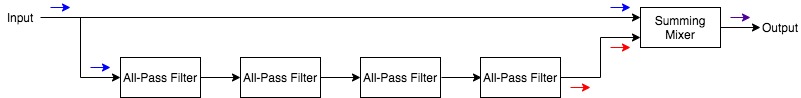
A phaser will work with two signal paths. One path will have a series of cascading all-pass filters, and the other will be a dry/unprocessed signal path. Mixing the two at the output will cause the phase cancellations that lead to the “notches” in the output.
For every 2 APFs, there will be 1 notch in the resulting frequency response of the output as certain frequencies fall out of phase. A simplified phaser signal path can be visualized with the following image:
The more all-pass filters (aka poles) there are, the more “notches” there will be in the phaser's output.
Let's have a look at the phase-shift graph for 1, 2, 3 and 4 pole setups:
The points at which the phase reaches 180º (or 540º, 900º and so on) will be the notches as the dry and phase-shifted signals are summed together at the phaser output.
The 4-pole frequency response would look something like this, where the 180º out-of-phase frequencies show up, effectively, as notch filters.:
The more poles, the more notches (at a two-to-one ratio).
If we were to modulate the corner frequency of each stage/pole upward and downward within the audible frequency spectrum, we would sweep these notches and have ourselves a phaser effect!
Feeding the final all-pass filter output back into the first all-pass filter input will further intensify the effect by producing resonances:

The locations of these notches along the resulting output frequency response are then modulated via an LFO (low-frequency oscillator) to cause a sweeping movement of the “EQ”.
And there we have, as concise and simple as I can make it. Here's an illustration of a simplified phaser signal path.

Common phaser effect controls include:
- Speed/Rate: controls the frequency of the LFO, which, in turn, controls the speed at which the comb-type filter will sweep across the signal’s EQ.
- Width: controls increase or decrease the amplitude of the LFO and, thereby, increase the range of frequencies the phaser will affect.
- Feedback/Resonance: adjusts the amount of the affected signal that is fed back through the phaser circuit, thereby increasing the resonance of each peak within the comb filter and increasing the intensity of the phaser effect.
- Stages/Poles: changes the number of poles (and therefore notches) in the phaser circuit/effect.
- Mix: adjusts the mix between the dry (unprocessed) signal and the wet (phase-shifted) signal.
- Notable 19″ rack mount phaser unit: Roland PH-830
- Notable phaser effect pedal: MXR Phase 90
- Notable phaser Eurorack module: Doepfer A-125 VC Phaser
- Notable phaser plugin: Eventide Instant Phaser Mk II

Call To Action!
Bookmark this article for future reference whenever you have questions on equalization.
Find a few go-to EQs or EQ plugins for your mixing and production endeavours—one of each style is a good idea (graphic, parametric, passive, dynamic, linear phase, mid-side)—and master their use thoroughly.
Have any thoughts, questions or concerns? I invite you to add them to the comment section at the bottom of the page! I'd love to hear your insights and inquiries and will do my best to add to the conversation. Thanks!


