Complete Guide To The Phaser Audio Modulation Effect

The phase of audio signals plays a critical role in how signals interact and come together in a mix. Phase-shifting, including the phaser effect, is a creative way to add sonic interest to audio signals. The phaser phase-shifting effect allows us to manipulate phase in a controlled and pleasing way to achieve a distinct modulation effect.
What is the phaser effect in audio? Phaser is a modulation audio effect whereby a series of peaks and troughs are produced across the frequency spectrum of the signal’s EQ. These peaks and troughs vary over time, typically controlled by an LFO (low-frequency oscillator), to create a sweeping effect known as phaser.
In this article, we'll discuss the phaser audio effect in great detail. We'll also learn about phase in general and a variety of different phaser effects units.
A Primer On Phase
Before we get into the phaser effect discourse, it's paramount that we understand what phase entails and how it affects audio signals.
In audio signals (and mathematics more generally), phase refers to the number of periods spanned by a variable of a periodic function. It is defined as an angle and can be expressed in radians or degrees, though degrees are much more commonly used in audio.
Audio signals, whether they're stored or active (or AC voltages or digital representations of such voltages), are periodic waveforms that represent/mimic sound waves. They, therefore, are subject to phase.
When discussing the phase of an audio signal waveform, we generally describe it with degrees. One full period of a waveform is defined as 360º. In repeating waveforms, such as those from an audio oscillator, the 360º will effectively restart the signal in a new period (denoted at 0º). Each multiple of 360º will mark a new period.
Sine waves, in audio, contain only the fundamental frequency and no partials/harmonics, making them the simplest audio signal to study.
To keep things as simple as possible in this article, we'll focus many of our examples on sine waves. A sinusoidal audio waveform will have an amplitude that can be expressed as some function involving the sine of the phase of the signal.
Here is an amplitude-time graph of a basic sine wave with various markers at important phase values:

Notice how, in a repeating waveform, the phase may continue above 360º but can also be defined between 0 and 360º relative to the next period/cycle.
Notice, too, that in particular sine waves above, the 90º and 270º points represent the maximum peak and minimum peak, respectively.
The general point I'm making here is that the phase of a repetitive waveform refers to a point within the wave cycle/period. A repetitive wave will go through 360º as it completes one period (one cycle).
The phase relates the amplitude (or another parameter) to time within a periodic waveform.
The frequency of a signal is defined in Hertz (Hz), which means cycles/periods per second. Since the universally accepted range of human hearing is from 20 Hz to 20,000 Hz, audio signals will often have frequency information within this frequency band.
Though a simple sine wave will have a single frequency and a repeating pattern, most audio signals will be made of various frequencies that are consistently changing in amplitude. So then, with complex audio signals, we may never see a repeat of a waveform period. However, phase still applies to these audio signals.
This is particularly true when it comes to phase shift.
Recap On Phase
Before moving on, let's quickly recap what's been discussed on phase in audio signals:
• Phase refers to the position within a waveform relative to the beginning of the waveform.
• When it comes to audio signals, phase is generally defined in degrees, and 360º refers to one full cycle/period of the waveform.
What Is Phase Shift?
Now that we understand what phase is, we'll turn our focus to phase shift, which is the key working principle in the phaser effect.
Just as we can use phase to define a specific point within a cycle/period of a waveform, we can also use phase to describe the phase shift (difference in timing) between two identical (or nearly identical) waveforms.
An acoustic example of this is when two microphones are set up to capture a single sound source. If the microphones are positioned at different distances and angles from the sound source, the sound waves will reach the microphones at different times and phases.
Though both mics are capturing the same sound, the waveforms will be different. This is potentially true of the amplitude and the timing/phase of the captured signals.
In signal processing, we can also shift the phase of a signal. This can be done explicitly with “phase flip” switches that reverse the polarity of a signal without affecting its time. It can be modulated by effects like phaser, flanger, chorus and vibrato.
Phase shift will also happen naturally in audio processors (particularly those that use reactive components in the signal lines of their circuits). Such is the case with EQ/filters.
Let's consider a few visual representations of phase shift, starting with an illustration of two sine waves with a phase shift of 90º.

As the red wave reaches 90º through its period, the blue wave is at 0º of its cycle.
Now let's consider a phase shift of 180º:

As the red wave reaches 180º through its period/cycle, the blue wave is at 0º of its period/cycle. 180º out-of-phase is also referred to as “out-of-phase.” That is because if we were to sum these two identical sine waves together, there would be no output.
To give you one more illustration, let's have a look at a representation of a 270º phase shift between, again, two otherwise identical sine waves:

Phase Shifting, Time & Frequency
I had mentioned previously that audio signals are generally not single sine waves. Rather, they are complex waveforms that typically occupy the frequency band between 20 Hz – 20,000 Hz (the limits of human hearing).
So then, to really understand how phase shifting and phasers work with audio, we must consider the factors of time and frequency when it comes to phase shifting.
We know that a full cycle/period of a waveform can be defined by 360º when discussing phase. However, the time it takes for that waveform to go through a full cycle is dependent on the frequency (or wavelength, which is inversely proportional to frequency) of the waveform.
Once again, frequency is measured in Hertz (Hz), which refers to cycles per second.
Again, we'll stay away from complex audio signals in our example illustrations. However, we'll consider different time and frequency values to understand how they relate to phase shift.
Let’s begin by looking at a 1 kHz (1,000 Hz) sine wave as an example.
A 1,000-cycles-per-second waveform will take 1 ms (0.001 seconds) to complete 1 cycle/period.
So if we took two identical 1 kHz sine waves and delayed one of them by 1 ms, we'd effectively cause a 360º phase shift. The shifted signal would be completely in phase with the other.

Now, if we cut the frequency in half, we'd have two identical 500 Hz sine wave signals. Each cycle/period would now take 2 ms of time. Delaying one signal by the same 1 ms would now only delay the signal by half its cycle and, therefore, cause a 180º phase shift. The shifted signal would be completely out-of-phase with the other.

With identical copies of a signal (and even with waveforms of similar shape), approaching 0º (or 360º) will make them more in-phase and increase/strengthen the output level. Conversely, approaching 180º will make them more “out-of-phase” and decrease/weaken the output level.
This strengthening and weakening of particular frequencies in the output is the essential effect of a phaser. In other words, the sound of a phaser is due to the cancelling out of out-of-phase frequencies within the overall audible band (20 Hz – 20,000 Hz).
Note that if we were to double the frequency value of our original 1 kHz to 2 kHz, we'd have 2,000 cycles/second or 1 cycle every 0.5 ms. Delaying this signal by 1 ms would also put the signals completely in phase with each other. The difference is that two cycles will pass before the second signal begins.

In fact, the following is true of sine waves: If we know the lowest frequency that will give us a perfectly in-phase phase shift (where the second copy of the signal starts at the end of the first cycle of the first copy), then any integer multiple of that frequency will also produce a 100% in-phase phase shift.
And what about the frequencies where a 1 ms delay would cause a 180º out-of-phase phase shift?
Well, these would happen at times where the phaser shifts half the waveform plus any integer multiple of the waveform.
Between 1 and 2 kHz, the frequency is 1.5 kHz, which has a period of 0.666 ms:

To generalize, we have the following equations to represent the 100% in-phase and 100% out-of-phase frequencies of a given sine wave.
\omega = 360 \cdot \frac{t}{p}where:
ω = phase shift (in degrees)
t = time difference between the original and shifted signal (in seconds)
p = period of the wave being shifted (in seconds)
Remember that if the ω = 360x (x is an integer number), then the shifted signal will be 100% in phase.
It the ω = 360x + 180 (x is any integer number), then the shifted signal will be 100% out-of-phase.
To keep with our example of a 1 ms delay/phase-shift, our in-phase frequencies would be:
- 1 kHz
- 2 kHz
- 3 kHz
- 4 kHz
- 5 kHz, and so on
Our out-of-phase frequencies would be:
- 500 Hz
- 1.5 kHz
- 2.5 kHz
- 3.5 kHz
- 4.5 kHz, and so on
This kind of phase filtering can be visualized across the entire frequency spectrum in the illustration below:

In the picture above, we see what is referred to as a comb filter. When a signal is mixed in with a phase-shifted version of itself, regularly spaced notches are created throughout its frequency response. These notches resemble a comb, hence the name.
Phase shifting of longer wavelengths (lower frequencies) requires longer delay times to cause significant cancellation.
A phaser will not produce a perfect comb filter. However, understanding the basics of phase-shifting and the idea of a comb filter is important when learning about phasers.
What Is The Phaser Effect?
The phaser effect is a type of modulation effect whereby the input signal is duplicated and phase-shifted. The phase-shifting is achieved via a series of cascading all-pass filters.
By modulating the phase shift of the duplicated signal with a low-frequency oscillator, the phaser will modulate the frequency values of the peaks and troughs over time in the resulting comb filter.
So, then, a phaser's effect is that of a sweeping series of notch filters across the signal's frequency content. Of course, there are no physical notch/band-stop filters in a phaser circuit. These sweeping “EQ cuts” are simply a result of the phase-shifting effect.
Explaining the phaser effect with words alone is not enough. I'd suggest finding music with the phaser effect in it or, for a cleaner example, phaser effects unit demos. Listening is the best way to understand the sonics of the effect. As for a description for the sound, I'd use the words “sweeping,” “modulated,” “filtering,” “trippy,” etc.
The All-Pass Filter
Most phase-shifting modulation effects will utilize a delay circuit and modulate the delay time of this circuit. Phasers do it differently by using all-pass filters to affect the phase of the signal.
What is an all-pass filter in audio? An all-pass filter allows all frequencies to pass with unchanged amplitude but will shift the phase across the output's frequency response. All-pass filters produce varying delays across the frequency response in order to produce this phase shift.
So at the surface level, an all-pass filter may seem useless. A filter that doesn't actually filter any frequencies? However, because filters introduce some amount of phase shifting (due largely to the reactive components within their circuits, i.e., capacitors), all-pass filters can effectively alter the signal phase without altering its frequency content.
An all-pass filter can be visualized in this simplified diagram:

The input signal is split. One copy is fed through a low-pass filter that removes high-end frequencies above a set cutoff frequency. The other copy is fed through a phase inverter (putting it 100% out-of-phase) and then runs through a high-pass filter that removes low-end frequencies below that same cutoff frequency.
These two copies are then summed together at the output. The frequency content remains the same as each filter passes what the other cuts. However, the phase of the summing mixer output is altered significantly.
Generally speaking, a single all-pass filter will cause a total of 180º phase-shift (due to the phase inverter) between the low-end and the high-end frequencies. So then, the amplitude-frequency and phase-frequency graphs of an all-pass filter would resemble the following:

The corner frequency (fC) refers to the cutoff frequency point of both the internal HPF and LPF. It marks the halfway point between the two phase-shift extremes (in this case 0º and 180º).
Phaser Circuit Design
Here's where we put everything together and learn how phasers actually work. We've discussed phase, phase-shift and all-pass filters and not we'll go through the basics of phaser design to understand how phasers work!
Cascading All-Pass Filters (Poles)
A phaser will effectively split the input signal into two paths.
One path will go direct to the summing mixer at the output of the unit. This is where the “direct” or “dry” signal will go. Remember, to achieve the phase cancellation of the phaser effect, we need a direct signal and phase-shifted signal to interact with each other.
The other path will be passed through a series of all-pass filters. As we've learned previously, each all-pass filter will pass all frequencies but alter the signal's phase across the frequency spectrum.
Each all-pass filter in cascade will cause an additional 180º of total phase-shifting across the output's frequency response. Each all-pass filter is referred to as a “pole” or “stage” when describing the phaser circuit.
As an example, let's consider a basic 4-pole/stage phaser. The basic signal flow chart would resemble the following:
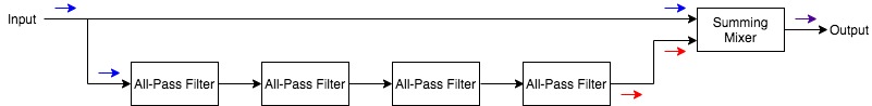
So with 4 poles, we would have a total phase shift of 720º from the low-end to the high-end.
Here's an illustration to help visualize the potential phase-shift-frequency graph of a 1, 2, 3 and 4-pole phaser. I've included points where the 180º trough points would occur in the resulting amplitude-frequency graph:

When summing the direct and phase-shifted signals together, this 4-pole phaser output would look something like this (assuming a 50/50 mix):

From the images above, we can infer that the more poles/stages we have in a phaser circuit, the more notches we'll have in the output frequency response. We can also tell that, as was mentioned previously, we're not dealing with a true comb filter!
Unless there's some initial offset in phase, a phaser has 1 notch for every two poles. If there is some sort of phase offset, there is a potential to achieve an additional notch with odd-number stages. This offset/odd-numbered staging is rare but worth mentioning.
Here's an example to help visualize a 3-pole phaser with 2 troughs. Note that the low-end does not start at 0º (there's a phase offset), and the resulting phase line passes through both 180º and 540º:

Analog phaser units will generally offer 2 to 12 stages/poles and typically only even number options. Some phasers offer odd-number stages/poles.
Digital phasers can offer many more stages if need be.
The Summing Mixer
The summing mixer's main purpose is to mix the direct and the phase-shifted signals together. It's the mixing of these signals, after all, that produces the phaser effect.
Thus far, we’ve been under the assumption that the summing amp would be mixing equal parts of the direct and phase-shifted signals.
This “50/50” is actually the optimal mix. When the direct and phase-shifted signals' amplitudes are equal, the out-of-phase frequencies will be completely cancelled out. This produces deeper notches in the resulting frequency response of the output and, therefore, a more pronounced sonic effect.
However, the mix of the two signals can often be adjusted to reduce the level of attenuation at the notches and lessen the phaser's overall effect.
LFOs, CVs & Modulation
A phaser wouldn't be a modulation effect if there were no modulation. In fact, without modulation, the phaser circuit would simply act as a series of stationary notch/band-stop filters.
To achieve the phaser effect, we have to make these notch/band-stop filters move. In other words, we must modulate the corner frequencies of the all-pass filters to sweep the resulting notches/band-stop filters across the frequency spectrum.
This is typically achieved, ultimately, via a low-frequency oscillator (LFO). As the name suggests, an LFO oscillates at low frequencies (those below the low-end audible limit of 20 Hz). The LFO will generally have a basic waveform like the sine wave, which we've seen in our many examples.
The LFO will generally control the variable resistance of a potentiometer which, in turn, will control the corner frequencies of the all-pass filters.
As the corner frequency of each all-pass filter is modulated upward and downward within the audible frequency spectrum, the output peaks and notches are also modulated up and down, creating the phaser effect!
Though LFOs are popular, control voltages (CVs) can also be used to vary the corner frequencies of certain phasers. CVs will act to control the variable resistance of a potentiometer similarly to the LFO.
Here is an updated version of the simplified phaser circuit knowing what we know now:

The frequency of the LFO determines the speed/rate of the sweeping effect of the phaser.
Note that a CV input signal can take the place of the LFO controller in the above diagram.
The Feedback Loop & Phaser Resonance
We're not done just yet. We also have to discuss the importance of the feedback loop in the phaser circuit.
Adding the feedback look to our simple phaser signal flow chart would give us the following:

The feedback control allows users to send some adjustable amount of the phase-shifted signal back into the phase-shifting part of the circuit.
By increasing the feedback, the phaser circuit will produce deeper cuts in the notches of the output signal and more noticeable resonances at the peaks of the signal.
This causes more pronounced resonances in the peaks of the output signal and a more distinct “phaser sound”.
Taking a second look at the aforementioned 4-pole phaser frequency response, we can compare no feedback (orange line) with some amount of feedback (blue line):

Note that the feedback loop is not delayed, and so the LFO will effectively modulate the dry and feedback signals to produce the same notches and peaks in the output signal.
Like any feedback circuit, too much can produce undesirable run-away effects. Keeping the feedback/resonance control at a safe amount is essential.
A Note On Stereo Phasers
Some phasers will double the fun with stereo outputs. These units can operate in one of two basic ways, depending on their inputs.
A phaser may send a mono input signal down two distinct phaser paths for the left and right stereo channels (each path have a direct and phase-shifted path in its own right).
One of the channels (let's say the right channel) will be phase-shifted relative to the other (let's say the left channel) to obtain a stereo effect from a mono input.
There will be two summing mixers (one for each channel) and a stereo output or two mono outputs (for the left and right channels).
If a phaser has a stereo input, then each channel may very well be processed by its own phaser circuit, which can produce some pretty wild results at the stereo output.
Phaser Parameters
Now that we understand what phase-shifting is and how a phaser achieves its effect, let's consider the several parameters that will essentially control how a phaser will perform.
Phaser effects units/plugins will often have many (if not all) of the following controls:
Speed/Rate
The speed/rate parameter of a phaser will control the frequency of the LFO. The frequency of the LFO, in turn, controls the speed at which the corner frequencies of the cascaded all-pass filters are modulated and, therefore, the rate at which the resulting comb-type filter sweeps across the signal’s frequency content.
With all other parameters being equal, a slower rate will produce a more subtle phase-shifting effect.
Width
The width parameter of a phaser controls the amplitude of the LFO and, therefore, the range of frequencies the phase-shifting effect will sweep through.
Feedback/Resonance
The feedback parameter controls the level/amount of phase-shifted signal that gets fed back through the phase-shifting circuit. By increasing the feedback, the resonance peak of each sweeping corner frequency will be accentuated.
This control is, therefore, often labelled as “resonance”.
Stages/Poles
Some phasers allow users to adjust the number of poles within the phase-shifting circuit. This is more common in computer-programmed phaser plugins.
By increasing the number of poles (the number of cascaded all-pass filters in the phase-shifting circuit), we increase the number of notches within the resulting phase-shift-induced “EQ.”
Remember that a phaser will produce 1 notch for every 2 poles. Increasing the number of poles will give a different, and arguably more obvious, phaser sound.
Mix
The mix parameter (sometimes referred to as the blend or amount control) will mix the direct/dry signal with the phase-shifted signal at the output.
Remember that to produce the phase cancellation that makes up the “phaser effect,” the direct and phase-shifted signal must be mixed together.
The phaser effect is technically the most pronounced when these two signals are mixed equally. This allows for maximum phase cancellation between the two signals.
Read the manual to find out what the mix control actually means. It’s often the case that having the control fully clockwise will get you to 50/50 (rather than having 50/50 be at 12 o’clock, as is the case in many other pedals.
Depth/Intensity
The depth or intensity parameter of a phaser could refer to different parameters.
The phaser effect is most prominent (with the deepest notches) when there is a 50/50 mix of the wet and dry signals, so depth could alter the mix.
It could also increase the amount of feedback within the all-pass cascade loop to increase the resonances of each peak in the phaser effect, thereby making the effect sound “deeper.”
This control could adjust multiple parameters in some instances. Read the manual to ensure you understand how the controls of your phaser affect its performance.
Phaser Effect Unit/Plugin Examples
Before we wrap things up, it's always a great idea to consider some examples. Let's have a look at 4 different phasers to help solidify our understanding of this modulation effect.
In this section, we'll discuss:
- 19″ rack-mounted phaser unit: Roland PH-830
- Phaser effect pedal: MXR Phase 90
- Phaser Eurorack module: Doepfer A-125 VC Phaser
- Phaser plugin: Eventide Instant Phaser Mk II
Roland PH-830
The Roland PH-830 is a beast of a phaser, but unfortunately, this rack-mounted unit has been discontinued.

The PH-830 was introduced in the late 1970s as part of Roland's RSS (Roland Studio System). This stereo phaser unit with two eight-stage phase shifters in parallel, with independent inputs, outputs, and CV inputs (for triggering and/or alternate control over the modulation).
Each of the stereo channels has controls for intensity (amplitude of the LFO), shift frequency (30 Hz – 10 kHz), and resonance (feedback amount).
Though there is only one LFO to be shared between the two channels, the PH-830's invert switch effectively flips the polarity of the LFO on the right channel. The waveform of the LFO can be set to sine, triangle, and sawtooth waveforms, and the LFO's frequency can be dialled in between 1 and 10 Hz.
MXR Phase 90
The MXR Phase 90 is one of the most popular phaser pedals ever to be produced.

This instantly recognizable orange box features a single knob labelled “Speed,” which controls the frequency of the LFO and, therefore, the rate of the sweeping phaser effect.
This phaser utilizes 4 stages and has 2 notches in the output.
Doepfer A-125 VC Phaser
The Doepfer A-125 VC Phaser is a superb 12-stage phaser module designed in the popular Eurorack format.

This phaser module is modulated via a control voltage (CV) input. Of course, this CV could easily be taken from an LFO module in the modular synth world. This unit's phase-shifting can also be controlled manually via the shift knob (when no control voltage is present).
The output level and resonance (feedback) can also be controlled. The mix knob is set up so that at 0, the output is a 50/50 blend of the direct and phase-shifted signal (the truest phaser signal). As the mix knob is turned up, more of the direct signal is added to the output in addition to the unchanged 50/50 phaser mix.
Eventide Instant Phaser Mk II
The Eventide Instant Phaser Mk II is an emulation of Eventide's groundbreaking Instant Phaser hardware unit that, when released in 1972, was the first-ever studio phaser.

This digital phaser plugin captures the unique analog character of the original. It even has an “Age” control that emulates the ageing of analog components.
This plugin offers three different flavours of phase-shifting: Shallow, Deep, and Wide. The depth control mixes the dry and phase-shifted signal together to increase or decrease the amount of phaser effect at the output.
The modulation of the Instant Phaser Mk II can be controlled in 4 different ways:
- Manual: allows precise automation of the phasing.
- Oscillator: modulates the phasing via an LFO that can be set to sync with a session, get re-triggered with new note information.
- Envelope: reads the amplitude envelope of the input signal (or a sidechain) and uses this envelope to modulate the phasing.
- Remote: maps the phasing control to a mod wheel for tactile manipulation.
This 8-pole phaser has feedback control and a stereo option as well.
Call To Action!
Experiment with phaser effects, whether they be plugins or hardware. Listen critically to how the modulation changes the sound over time. Adjust the parameters to get a sense of the extremes.
Find and listen to songs that utilize the phaser effect to really internalize its sound and how it's used.
Have any thoughts, questions or concerns? I invite you to add them to the comment section at the bottom of the page! I'd love to hear your insights and inquiries and will do my best to add to the conversation. Thanks!
Related Questions
What's the difference between phaser and flanger? Phasers and flanger both produce their sonic effect by introducing phase-shifting into a signal and controlling such phase-shifting with an LFO. To achieve their effects, phasers utilize all-pass filters and modulate the corner frequencies, while flangers utilize a delay circuit and modulate the delay time.
What are audio modulation effects? Audio modulation effects manipulate the input audio over time via the control of a carrier signal. The input audio is referred to as the modulator signal, which technically controls the carrier signal, which is generally produced via an oscillator generator or signal detector.
Related Articles
To learn more about flanger and modulation effects more generally, check out the following articles:
• Complete Guide The Flanger Audio Modulation Effect
• Complete Guide To Audio Modulation Effects (With Examples)


